Electric power steering system and controller of the electric power steering system

a technology of electric power steering and controller, which is applied in the direction of steering initiation, instruments, vessel construction, etc., can solve the problems of inability to provide a proper steering assist force to the steering mechanism, difficulty or inability to reverse input by disturbance, and inability to accurately determine the direction of steering, etc., to achieve the effect of improving steering feel and steering stability

Active Publication Date: 2013-09-12
HITACHI ASTEMO LTD
View PDF0 Cites 21 Cited by
  • Summary
  • Abstract
  • Description
  • Claims
  • Application Information

AI Technical Summary

Benefits of technology

[0005]It is therefore an object of the present invention to provide an electric power steering system and a controller of the electric power steering system, which is capable of correctly judging the normal input and the reverse input and providing the proper steering assist force to the steering mechanism from the electric motor, which allows improvement in the steering feel and steering stability.

Problems solved by technology

In the electric power steering system of JP2010-036720, however, since the judgment is made only by the rate of change of the detection signal of the torque sensor or the steering angle sensor, an accurate or a correct judgment about whether the detection of the torque sensor or the steering angle sensor is the normal input according to the driver's intention or the reverse input by disturbance is difficult or impossible.
As a consequence, it is not possible to provide a proper steering assist force to the steering mechanism from the electric motor.

Method used


Image

  • Electric power steering system and controller of the electric power steering system
  • Electric power steering system and controller of the electric power steering system
  • Electric power steering system and controller of the electric power steering system

Examples


embodiment 1

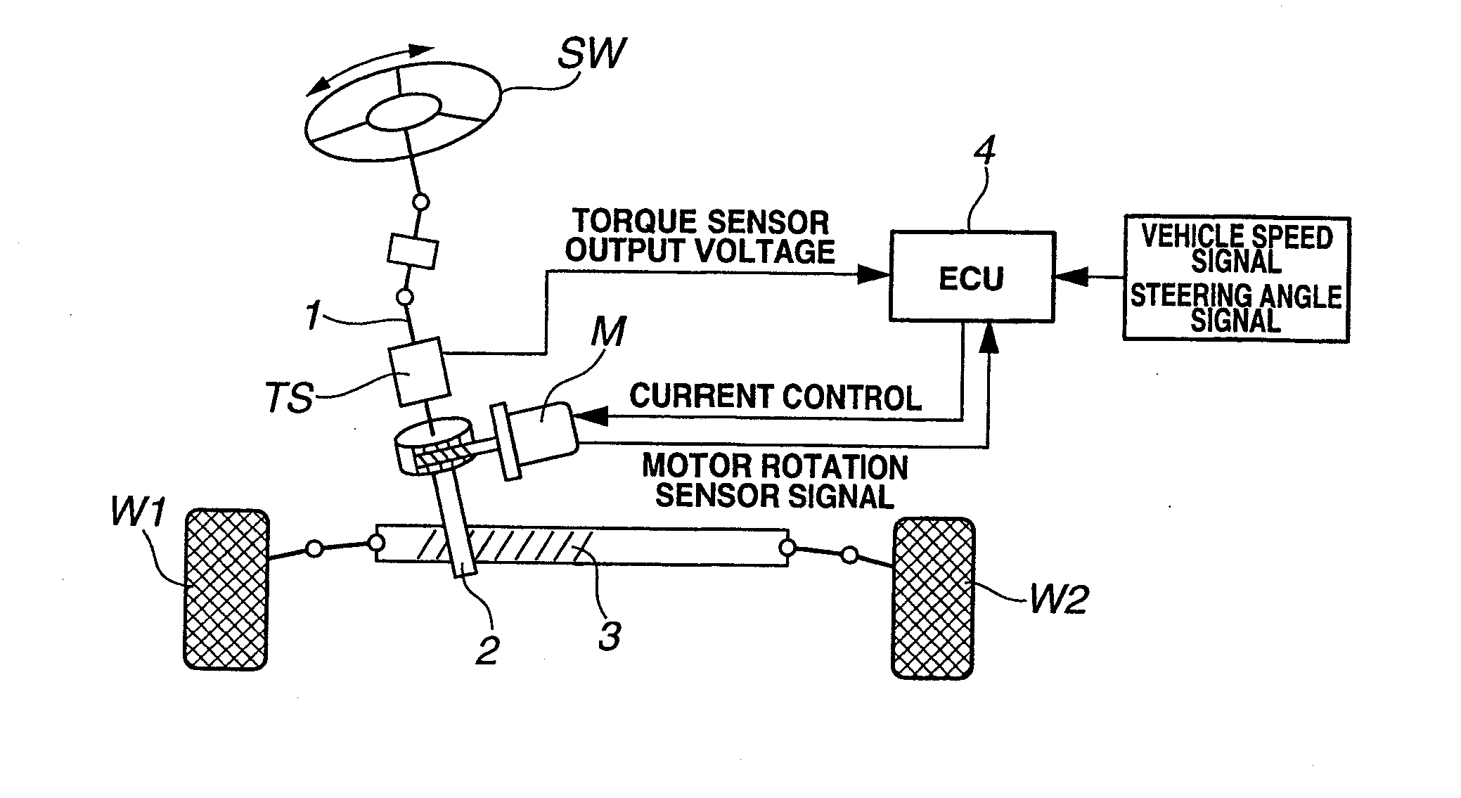
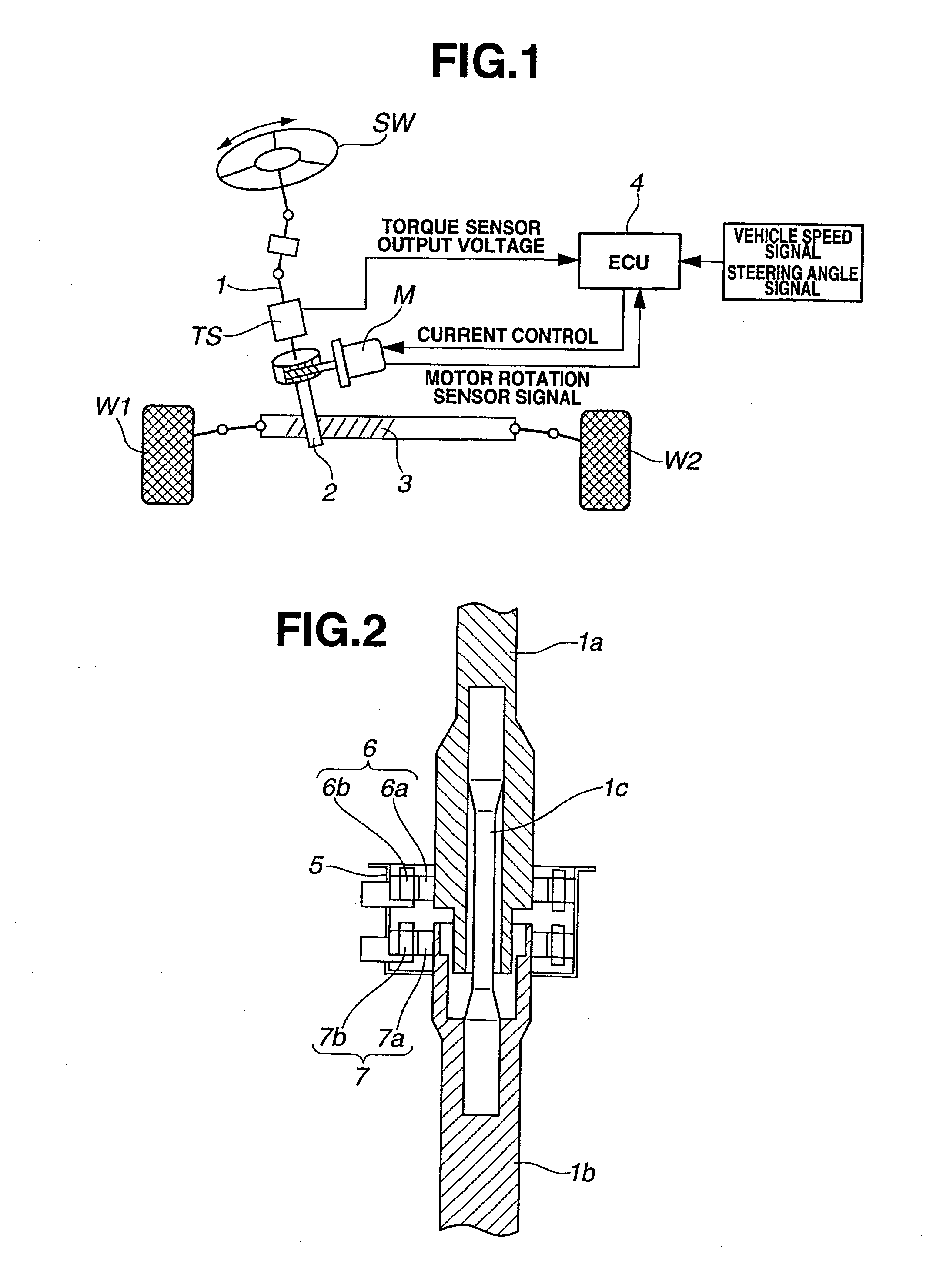
[0021]FIG. 1 is a schematic view of an electric power steering system of an embodiment 1 of the present invention. In the electric power steering system shown in FIG. 1, a basic steering mechanism is formed by a steering wheel SW, a steering shaft 1, a pinion shaft 2 and a rack shaft 3. This steering mechanism is configured so that when the steering wheel SW is turned by driver's steering operation, the rotation of the steering wheel SW is transmitted to the pinion shaft 2 through the steering shaft 1, and a rotary motion of the pinion shaft 2 is converted to a rectilinear motion of the rack shaft 3, then right and left steered road wheels W1 and W2 that are connected to both shaft ends of the rack shaft 3 are steered. That is, the rack shaft 3 is provided, on a surface thereof, with rack teeth (not shown) with which the pinion shaft 2 engages, and by the engagement between the rack teeth and the pinion shaft 2, a conversion mechanism that converts the turning of the steering shaft ...

embodiment 2

[0061]An electric power steering system of an embodiment 2 of the present invention will be explained. The structure and the configuration of the electric power steering system and the ECU 4 of the embodiment 2 are basically same as those of the embodiment 1, so their explanation is omitted here. In the embodiment 2, the friction compensation value is different from that of the embodiment 1.

[0062]FIGS. 7 and 8 are time charts showing the friction compensation values.

[0063]FIG. 7 shows a case where the input shaft side rotation angle signal S1 and the output shaft side rotation angle signal S2 change in the same direction with a difference existing between them, and also the change of the input shaft side rotation angle signal S1 is advanced with respect to that of the output shaft side rotation angle signal S2. In this case, as same as the embodiment 1, it is judged that the steering operation according to the driver's intention is performed, and the driver's intention flag is raise...

embodiment 3

[0069]An electric power steering system of an embodiment 3 of the present invention will be explained. The structure and the configuration of the electric power steering system and the ECU 4 of the embodiment 3 are basically same as those of the embodiment 1, so their explanation is omitted here. In the embodiment 3, the correction of the command current is different from the embodiment 1.

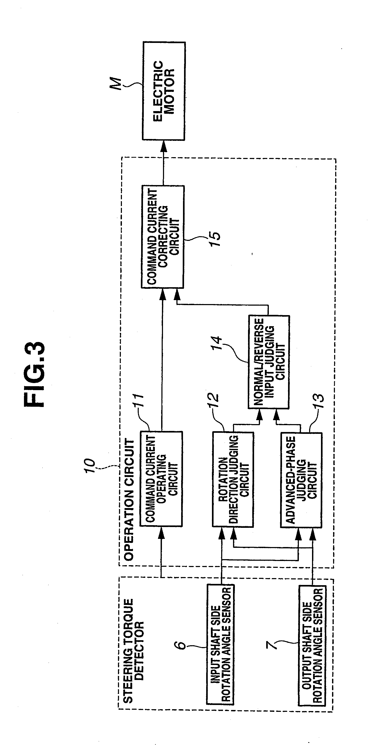
[0070]FIG. 9 is a time chart showing the correction of the command current of the embodiment 3. As shown in FIG. 9, the input shaft side rotation angle signal S1 does not change, but the output shaft side rotation angle signal S2 pulsates. That is, although the steered road wheels W1 and W2 pulsate under the influence of the disturbance, since the driver firmly holds or grips the steering wheel SW, the input shaft 1a side does not rotate. At this time, the normal / reverse input judging circuit 14 judges that the input state is the reverse input by the disturbance, and no driver's intention flag is r...


PUM


Abstract

Electric power steering system has steering mechanism; input and output shaft side rotation angle sensors detecting rotation angles of input and output shafts; operation circuit calculating command current for an electric motor; rotation direction judging circuit judging whether rotation directions of the input and output shafts are identical; advanced-phase judging circuit judging which phase of input and output shaft side rotation angle signals (S1, S2) is advanced; normal / reverse input judging circuit judging that (i) when both rotation directions are identical and S1 is advanced, input is normal input and (ii) when both rotation directions are identical and S2 is advanced, input is reverse input; and command current correcting circuit. The command current correcting circuit corrects the command current so that when the normal input is judged, torque in the same direction as input shaft rotation direction generated by the electric motor is greater than a case of reverse input judgment.

Description

BACKGROUND OF THE INVENTION[0001]The present invention relates to an electric power steering system and a controller of the electric power steering system, which provides a steering assist force to a steering mechanism of a vehicle with an electric motor being a driving source.[0002]In recent years, there have been proposed and developed various electric power steering systems. In the electric power steering systems, a rotation angle of an input shaft which rotates by driver's steering operation of a steering wheel and a rotation angle of an output shaft to which the rotation of the input shaft is transmitted are detected by a detector such as a torque sensor, and on the basis of this detection signal of the torque sensor, torque is transmitted to the steering mechanism of the vehicle from the electric motor. In this manner, the electric power steering system performs the steering assist.[0003]In one such electric power steering system, a judgment is made as to whether a detection (...

Claims


Application Information

Patent Timeline
Patent Type & Authority Applications(United States)
IPC IPC(8): B62D5/04
CPCB62D5/0463
Inventor KODATO, MASAKIYAMANO, KAZUYASUGIYAMA, YOSHITAKAYOSHITAKE, ATSUSHI
Owner HITACHI ASTEMO LTD
Why Eureka
Try Eureka