Pneumatic tire

Inactive Publication Date: 2011-04-21
SUMITOMO RUBBER IND LTD
View PDF12 Cites 21 Cited by
  • Summary
  • Abstract
  • Description
  • Claims
  • Application Information

AI Technical Summary

Benefits of technology

[0007]It is therefore, an object of the present invention to provide a pneumatic tire, in which the block rigidity

Problems solved by technology

In each method, however, it is inevitable that the tread grooves' volume is decreased.
Accordingly, there is a possibility that drainage of the tread groove

Method used


Image

  • Pneumatic tire
  • Pneumatic tire
  • Pneumatic tire

Examples


Example

[0017]Embodiments of the present invention will now be described in detail in conjunction with the accompanying drawings.

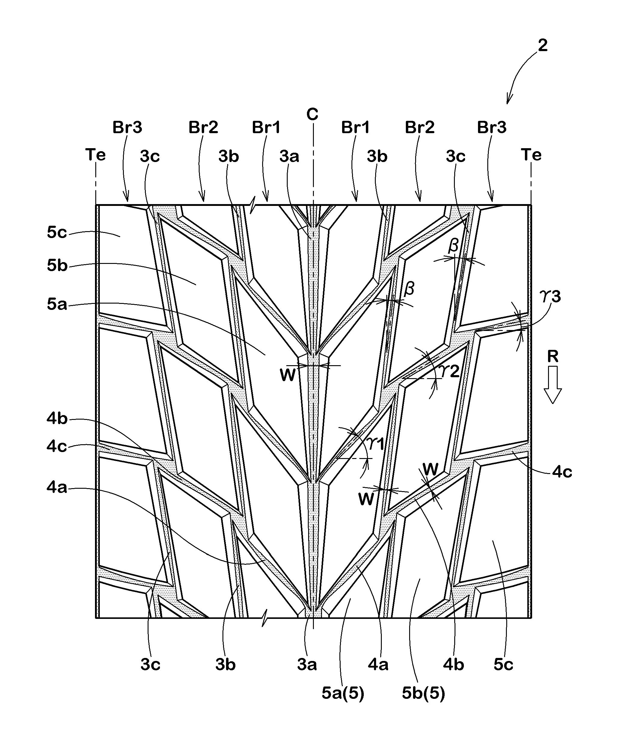
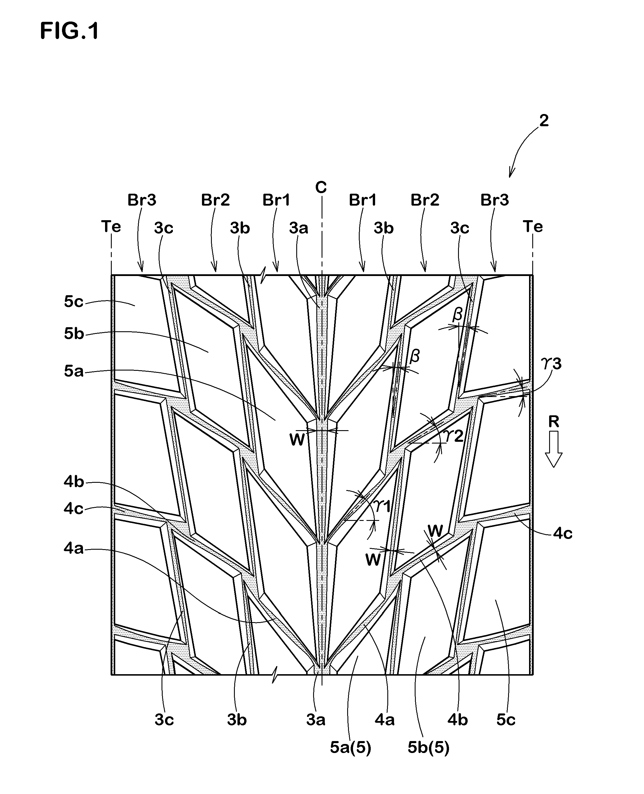
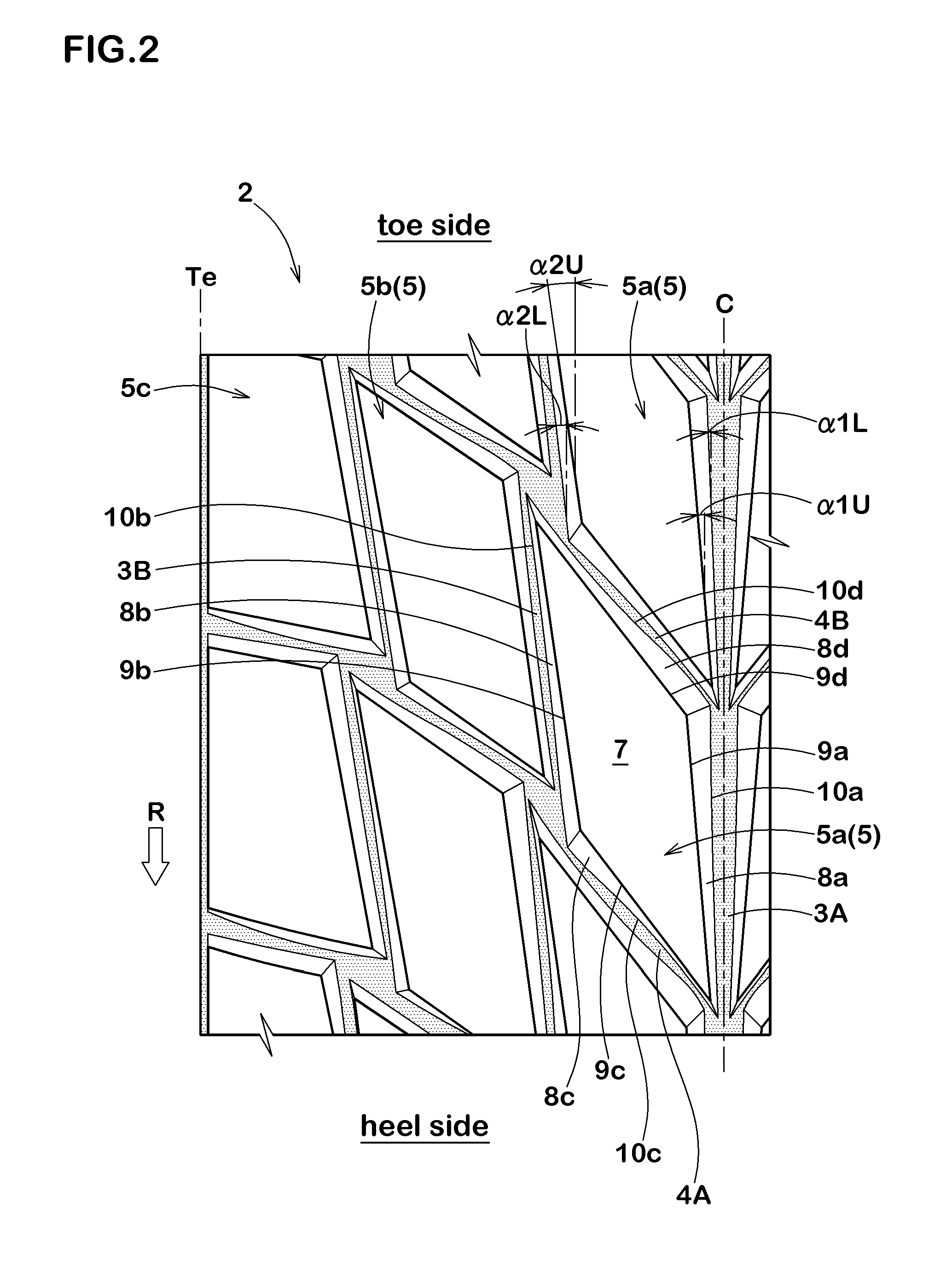
[0018]According to the present invention, pneumatic tire comprises a tread portion 2 provided on each side of the tire equator C with a plurality of blocks 5 in at least one circumferential row.

[0019]Each of the blocks 5 is defined by an equator-side longitudinal groove 3A, a tread-edge-side longitudinal groove 3B, a heel-side transverse groove 4A, and a toe-side transverse groove 4B which grooves continue to surround the block 5.

[0020]The meanings of the expressions “equator-side”, “tread-edge-side”, “heel-side” and “toe-side” are as follows:[0021]“equator-side”: axially inside with respect to the concerned block[0022]“tread-edge-side”: axially outside with respect to the concerned block[0023]“heel-side” and “toe-side”; one side and the other side with respect to the concerned block in one circumferential direction

Thus, the equator-side longitudinal groove 3A and...


PUM


Abstract

A pneumatic tire has tread blocks (5) each defined by an equator-side longitudinal groove (3A), a tread-edge-side longitudinal groove (3B), a heel-side transverse groove (4A) and a toe-side transverse groove (4B). The block (5) has an equator-side longitudinal wall surface (8a) having a first radially outer edge (9a) and a first radially inner edge (10a), and a tread-edge-side longitudinal wall surface (8b) having a second radially outer edge (9b) and a second radially inner edge (10b). The angle α1U of the first radially outer edge (9a), the angle α1L of the first radially inner edge (10a), the angle α2U of the second radially outer edge (9b) and the angle α2L of the second radially inner edge (10b), each with respect to the tire circumferential direction, satisfy the following four conditional expressions: (0≦α1L<α1U≦45); (0<α2L<α2U≦45); (α1L<α2L) and (α1U<α2U).

Description

BACKGROUND OF THE INVENTION[0001]The present invention relates to a pneumatic tire with tread blocks, more particularly to a configuration of the block capable of improving the block rigidity without sacrificing the drainage performance.[0002]In the pneumatic tires provided in the tread portion with a block pattern formed by a plurality of blocks, the following methods have been employed in order to increase the rigidity of the blocks to thereby improve the steering stability of the tire and the wear resistance of the tread portion:[0003]to increase the land ratio the block pattern (namely, to form the tread grooves with narrow widths);[0004]to form the tread grooves with shallow depths; and / or[0005]to form the wall surfaces (or side walls) of the blocks with gentle slopes.[0006]In each method, however, it is inevitable that the tread grooves' volume is decreased. Accordingly, there is a possibility that drainage of the tread grooves, specifically aquaplaning performance, is deterio...

Claims


Application Information

Patent Timeline
IPC IPC(8): B60C11/03
CPCB60C11/1315B60C11/0302B60C11/1392
Inventor IMAKITA, TAKESHIUEDA, KENJI
Owner SUMITOMO RUBBER IND LTD
Why Eureka
Try Eureka