Stabilizer bushing for vehicle

a technology for stabilizing bushings and vehicles, which is applied in the direction of shock absorbers, torsion springs, transportation and packaging, etc., can solve the problems of insufficient elastic deformation to secure effective damping characteristics or difficult to secure effective damping characteristics, and achieves effective equalization, small inner cavity section width, and excellent damping characteristics.

Active Publication Date: 2012-10-23
TOYOTA JIDOSHA KK +1
View PDF24 Cites 22 Cited by
  • Summary
  • Abstract
  • Description
  • Claims
  • Application Information

AI Technical Summary

Benefits of technology

[0011]The present invention has been made in the light of the situation described above. It is therefore an object of the invention to provide a stabilizer bushing that is improved to advantageously obtain a structure in which smooth rotation of a stabilizer bar inserted into an inner bore of a bushing body without being bonded to the inner bore can always stably be secured, regardless of structure and kind of a sliding member fixed to an inner circumferential surface of the bushing body, thereby effectively reducing torsional friction between the inner circumferential surface of the bushing body and an outer circumferential surface of the stabilizer bar, and in which the thickness of an inner rubber portion which is positioned at an inner side of the partition member is equal in a circumferential direction.
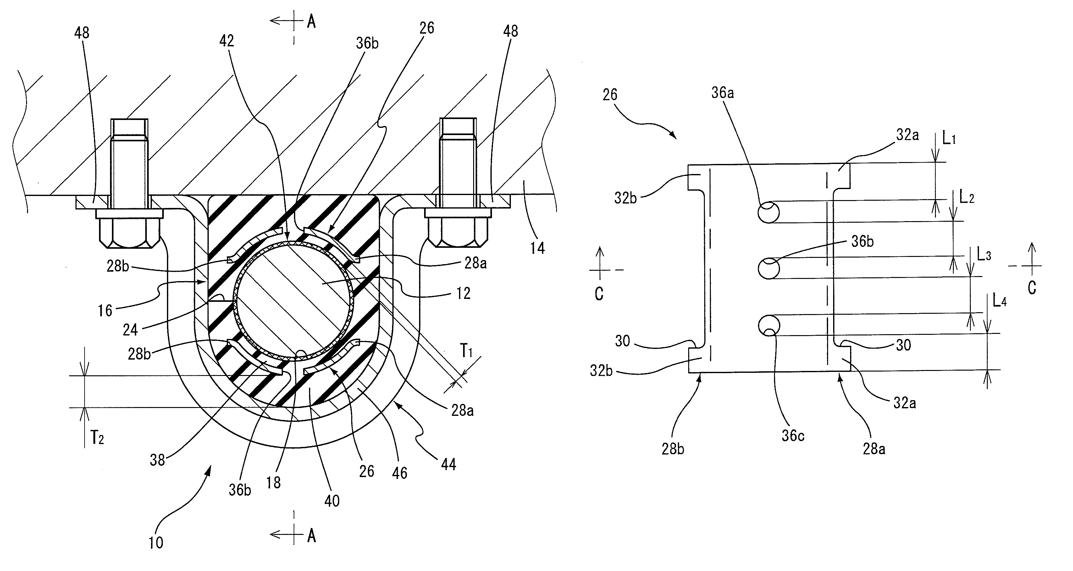
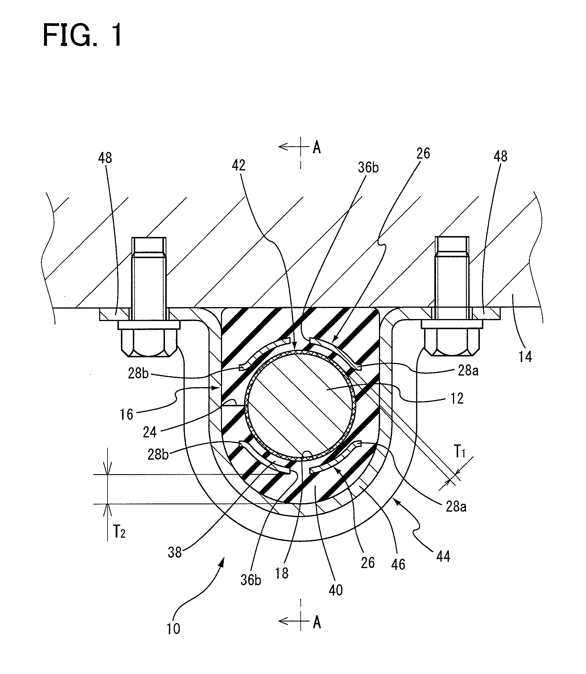
[0025]In the stabilizer bushing for a vehicle of the present invention, the two partition members each having a semi-tubular shape are embedded at a middle area in the axial direction of the bushing body so as to correspond to each other in the vertical direction and the thin inner rubber portion is made so as not to be subjected to elastic deformation against an applied load, especially a load applied in the direction perpendicular to the axis. Thus, the inner rubber portion is not elastically deformed when the load in the vertical direction is applied to the bushing body in a state where the stabilizer bushing is mounted on the vehicle. As a result, even if the sliding member fixed to the inner circumferential surface of the inner rubber portion (inner bore) is a liner cloth that is made of a cloth having a surface lubricity, it is effectively prevented that the liner cloth is undulated or rumpled by the elastic deformation of the inner rubber portion. Consequently, unlike the conventional stabilizer bushing, when the load in the vertical direction of the bushing body is applied, the sliding properties against the stabilizer bar may not be varied in the circumferential direction of the sliding member composed of the liner cloth, thereby always stably securing the smooth rotation of the stabilizer bar in the torsional direction.
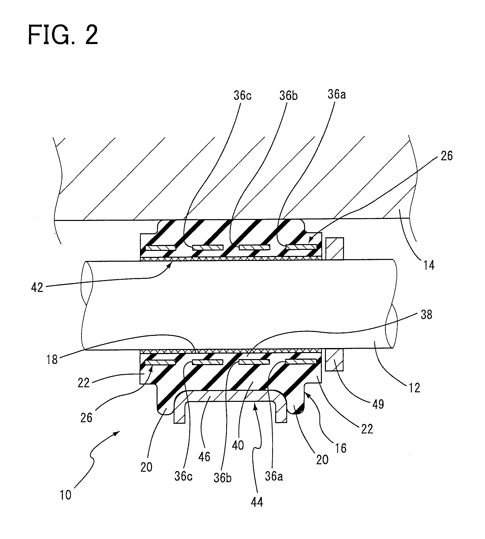
[0028]Therefore, in the stabilizer bushing for a vehicle of the present invention, it can effectively be prevented that, at the time of the vulcanization molding of the bushing body, the unvulcanized rubber does not partly fill the inner cavity section that results in the variation in the thickness of the inner rubber portion. Further, when the sliding member is composed of the liner cloth made of cloth (fabric), the pressure applied to the sliding member based on the flow pressure of the unvulcanized rubber flowing in the inner cavity section can be advantageously reduced and effectively equalized on the whole of the outer circumferential surface of the sliding member, at the time of the vulcanization molding of the bushing body. Consequently, in spite of that the width of the inner cavity section is small because of the small thickness of the inner rubber portion, it can effectively be prevented that the sliding member is fixed to the inner rubber portion while being partially undulated or rumpled by the flow pressure of the unvulcanized rubber, and that a rubber film is formed on an inner rubber portion by a part of the unvulcanized rubber oozed from the inner circumferential surface of the sliding member, at the time of the formation of the bushing body by vulcanization. As a result, there is no risk of variation in the sliding properties against the stabilizer bar in the circumferential direction of the sliding member, which is caused by undulation or rumple of the sliding member or a rubber film or the like on the inner circumferential surface of the sliding member, whereby the smooth rotation of the stabilizer bar in the torsional direction can always be secured.
[0029]Thus, in the stabilizer bushing for a vehicle of the present invention, the thickness of the inner rubber portion positioned at the inner side of the partition member is made equal in the circumferential direction, thereby stably fixing the sliding member to the inner rubber portion and securing excellent damping characteristics. Further, regardless of the structure of the sliding member fixed to the inner circumferential surface of the inner bore of the bushing body, the torsional friction between the inner circumferential surface of the bushing body and the outer circumferential surface of the stabilizer bar can effectively and stably be reduced. Consequently, the generation of noise caused by the rotation of the stabilizer bar in the torsional direction can effectively be prevented and excellent driving comfort of the vehicle can effectively be secured.
[0030]In the stabilizer bushing for a vehicle of the present invention, the two partition members are embedded into the middle area in the axial direction of the bushing body, thereby preventing the elastic deformation of the inner rubber portion against the load applied in the direction perpendicular to the axis. Thus, hysteresis in load-deflection properties of the spring of the bushing body as a whole can effectively be lowered. As a result, steering stability of the vehicle on which the stabilizer bushing of the present invention is mounted can effectively be improved.

Problems solved by technology

The expression “thickness that is not elastically-deformed” includes not only the thickness that is not deformed, but also the thickness that is deformed a little but the amount of the elastic deformation is not enough to secure the effective damping characteristics or difficult to secure the effective damping characteristics.

Method used


Image

  • Stabilizer bushing for vehicle
  • Stabilizer bushing for vehicle
  • Stabilizer bushing for vehicle

Examples


Embodiment Construction

[0043]To further clarify the present invention, there will be described in detail an embodiment of the invention with reference to the accompanying drawing.

[0044]Referring to FIG. 1 and FIG. 2, a stabilizer bushing for an automobile is shown as one embodiment of a stabilizer bushing for a vehicle of the present invention in a cross sectional view taken along the line perpendicular to the axis and in an axial cross sectional view, respectively. As apparent from FIG. 1 and FIG. 2, a stabilizer bushing 10 is assembled to a stabilizer bar 12 of the automobile and elastically supports the stabilizer bar 12 on a body 14 of the automobile. The stabilizer bushing 10 includes a bushing body 16 made of an elastic body.

[0045]More specifically described, the bushing body 16 is a tubular member as a whole having an inner bore 18 extending in the axial direction as shown in FIG. 3 and FIG. 4. The bushing body has an outer circumferential surface consisting of a substantially semi-cylindrical surf...


PUM


Abstract

A stabilizer bushing is provided which effectively reduces a torsional friction between a bushing body and a stabilizer bar. The stabilizer bushing includes a bushing body 16 made of a tubular elastic body, a sliding member 42 fixed to an inner circumferential surface of the tubular elastic body, and two partition members 26, 26 embedded in and bonded to a radially middle area of the bushing body 16. The partition members 26, 26 divide the bushing body 16 into an inner rubber portion 38 that is thin enough not to be elastically-deformed by a load applied thereto and an outer rubber portion 40 that is thicker than the inner rubber portion 38. Further, each of the partition members 26, 26 includes through holes 36a, 36b, 36c that are located so as to divide the partition member into a plurality of sections both in the axial and circumferential directions.

Description

[0001]This application is a continuation of the International Application No. PCT / JP2011 / 051711, filed Jan. 28, 2011, which claims the benefit under 35 U.S.C. §119(a)-(d) of Japanese Application No. 2010-018362, filed Jan. 29, 2010, the entireties of which are incorporated herein by reference.TECHNICAL FIELD[0002]The present invention relates to a stabilizer bushing for a vehicle. More particularly, the present invention relates to an improved structure of a stabilizer bushing for a vehicle that elastically supports a stabilizer bar on a vehicle body, while the stabilizer bar is inserted into an inner bore of the stabilizer bushing without bonding to the inner bore.BACKGROUND ART[0003]As is well known, a stabilizer bar is mounted on a vehicle such as an automobile for the purpose of suppressing tilting of a vehicle body, which is occurred at a turn or the like of the vehicle. Generally, the stabilizer bar is mounted to the vehicle body by means of a stabilizer bushing (vibration dam...

Claims


Application Information

Patent Timeline
Patent Type & Authority Patents(United States)
IPC IPC(8): B60G21/055B60G11/22F16F1/44F16F1/40F16F7/00F16F1/16
CPCB60G21/0551B60G2204/41B60G2204/1222B60G2202/135F16F1/3842F16F1/3876
Inventor KATO, KAZUHIKONAGAI, HIROAKIYANAGINO, HIDEOOKADA, KATSUZOKOBAYASHI, KOUICHIHOMMA, YUJIHAYASHI, SHINJI
Owner TOYOTA JIDOSHA KK
Why Eureka
Try Eureka