

Pneumatic tire
a technology of pneumatic tires and tyres, which is applied in the direction of tyre tread bands/patterns, vehicle components, transportation and packaging, etc., can solve the problems of large wear, irregular wear of the main land portion, and possible breakage of the contact end side, so as to improve the irregular wear resistance
Inactive Publication Date: 2018-05-17
TOYO TIRE & RUBBER CO LTD
View PDF3 Cites 3 Cited by
- Summary
- Abstract
- Description
- Claims
- Application Information
AI Technical Summary
Benefits of technology
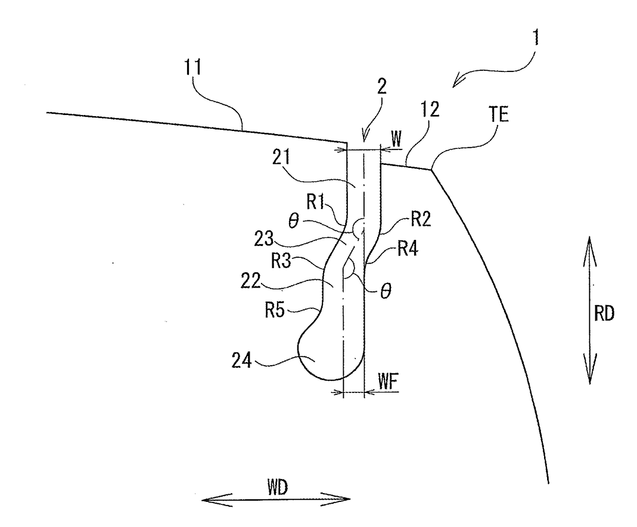
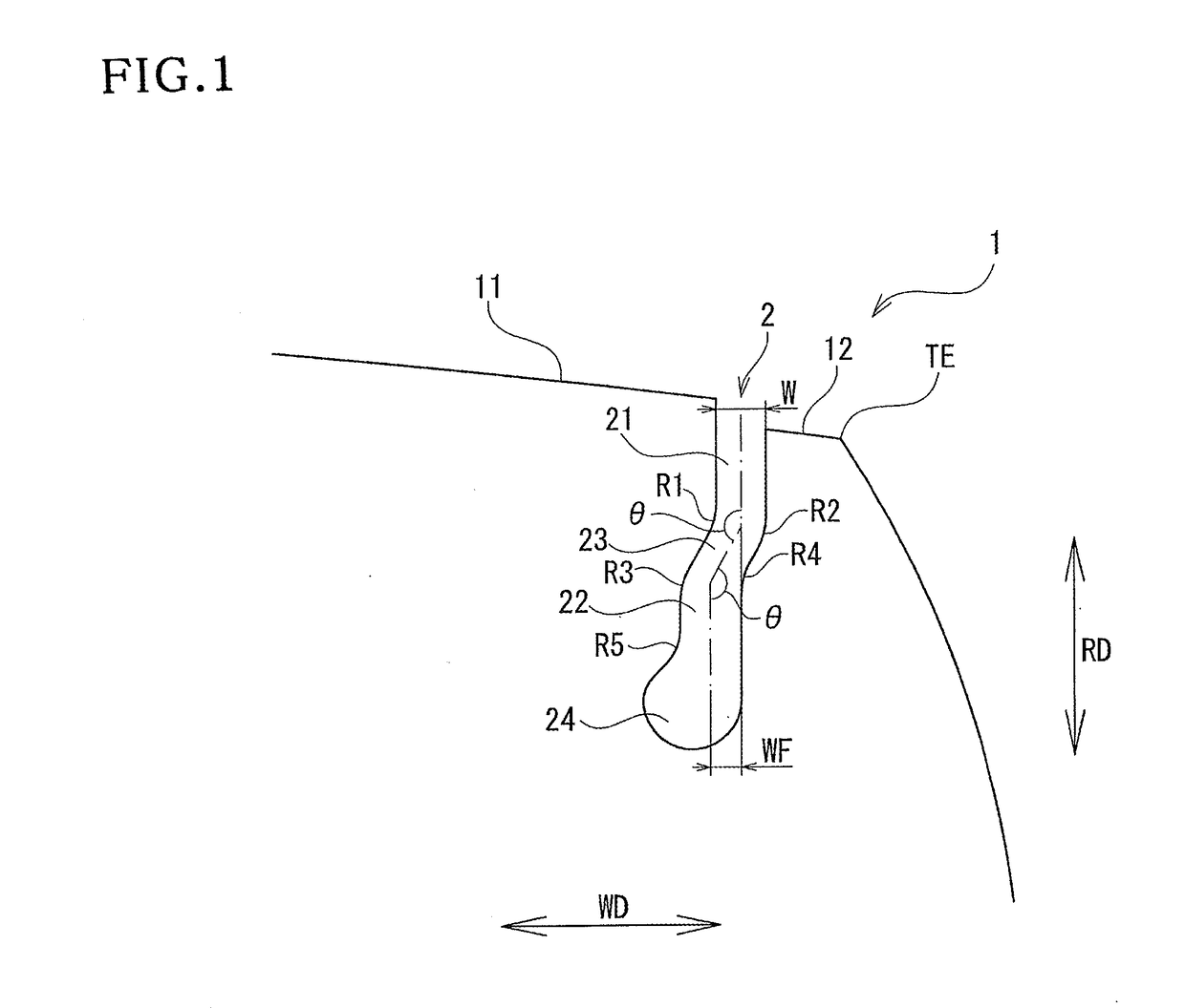
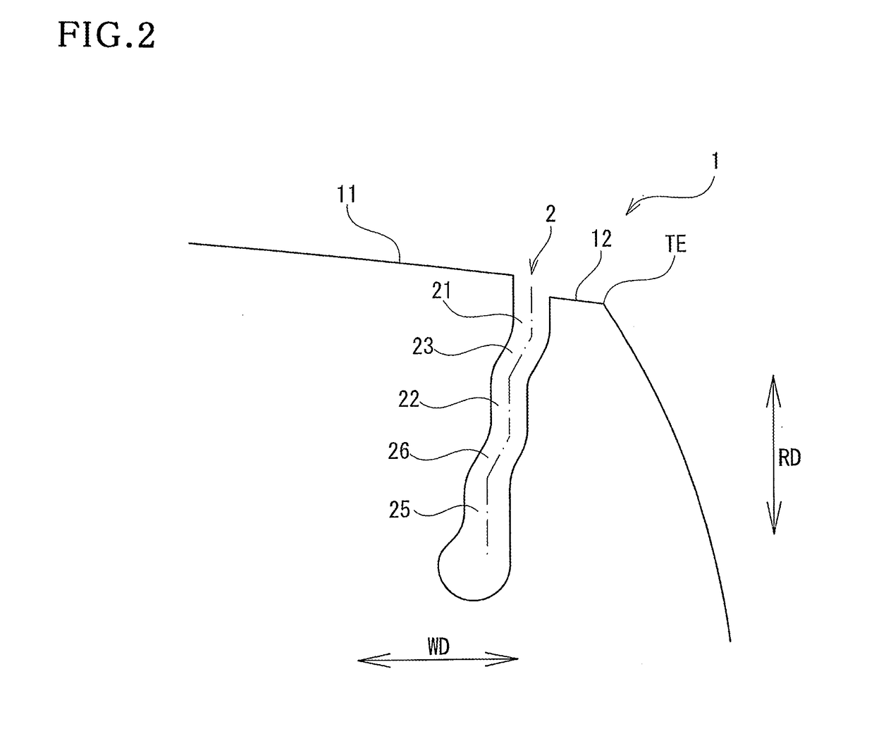
The present invention provides a pneumatic tire with improved resistance to irregular wear and cracking. The tire has a second groove portion closer to the tire equatorial plane side than the first groove portion, which reduces ground contact pressure and makes the tire flexible at the narrow groove positions. The second groove portion also increases the rigidity of the sub land portion, enhancing the tire's ability to suppress uneven wear and prevent cracking. The second groove portion also helps to prevent stones from getting stuck in the narrow groove. The angle formed by the first and second groove portions and the coupling portion is important for effective crack prevention. The distance between the groove width center of the first and second groove portions is also important for improving uneven wear resistance.
Problems solved by technology
As a result, there may be generated a problem that an amount of wear becomes great in the vicinity of the ground contact end of the shoulder land portion in comparison with the other land portions of the tread surface.
However, even if the narrow groove is provided, the ground contact pressure becomes higher in the portion near the narrow groove in the main land portion in the tire equatorial plane side, thereby newly causing the irregular wear within the main land portion.
Further, the sub land portion in a ground contact end side may be broken due to the deformation applied to the sub land portion during the traveling, and the effect of suppressing the irregular wear on the basis of the narrow groove may be lost.
Method used
View moreImage
Smart ImageViewing Examples

Examples
example 1
[0038]The pneumatic tire having the shoulder land portion 1 provided with the narrow groove 2 shown in FIG. 1 was manufactured. The result obtained by carrying out the above evaluation by using the pneumatic tire is shown in Table 1.
examples 2 to 5
[0039]The pneumatic tire having the same structures as the example 1 except the structure in which the angle θ formed by the first groove portion 21 and the coupling portion 23 and the angle θ formed by the second groove portion 22 and the coupling portion 23 are differentiated from the example 1 was manufactured. The result obtained by carrying out the above evaluation by using the pneumatic tire is shown in Table 1.
Login to View More PUM
 Abstract
A pneumatic tire includes a shoulder land portion and a narrow groove in a tread surface. The narrow groove extends in the tire circumferential direction and sections the shoulder land portion into a main land portion and a sub land portion. A first groove portion extends from the tread surface toward an inner side in the tire radial direction in parallel to the tire equatorial plane. A second groove portion is provided closer to the inner side in the tire radial direction and the tire equatorial plane side than the first groove portion and extends in parallel to the tire equatorial plane. A coupling portion is connected to an end portion of the first groove portion in the inner side in the tire radial direction and an end portion of the second groove portion in the tread surface side.
Description
BACKGROUND OF THE INVENTIONField of the Invention[0001]The present invention relates to a pneumatic tire having a shoulder land portion, and a narrow groove sectioning the shoulder land portion into a main land portion in the tire equatorial plane side and a sub land portion in the ground contact end side.Description of the Related Art[0002]In a pneumatic tire under traveling, a ground contact pressure generally tends to become higher in the vicinity of a ground contact end in a shoulder land portion of a tread surface. As a result, there may be generated a problem that an amount of wear becomes great in the vicinity of the ground contact end of the shoulder land portion in comparison with the other land portions of the tread surface. As a method of preventing the irregular wear as mentioned above, it has been carried out to provide a narrow groove extending in a tire circumferential direction closer to an inner side in a tire width direction than the ground contact end, in the vici...
Claims
Login to View More Application Information
Patent Timeline
 IPC IPC(8): B60C11/03B60C11/13
CPCB60C11/0327B60C11/1307B60C11/0306B60C2011/0348B60C2011/1361B60C2011/013B60C11/01B60C11/1353B60C2011/1338B60C2011/133B60C11/1315
InventorYOKOMAKURA, SEIJI
OwnerTOYO TIRE & RUBBER CO LTD