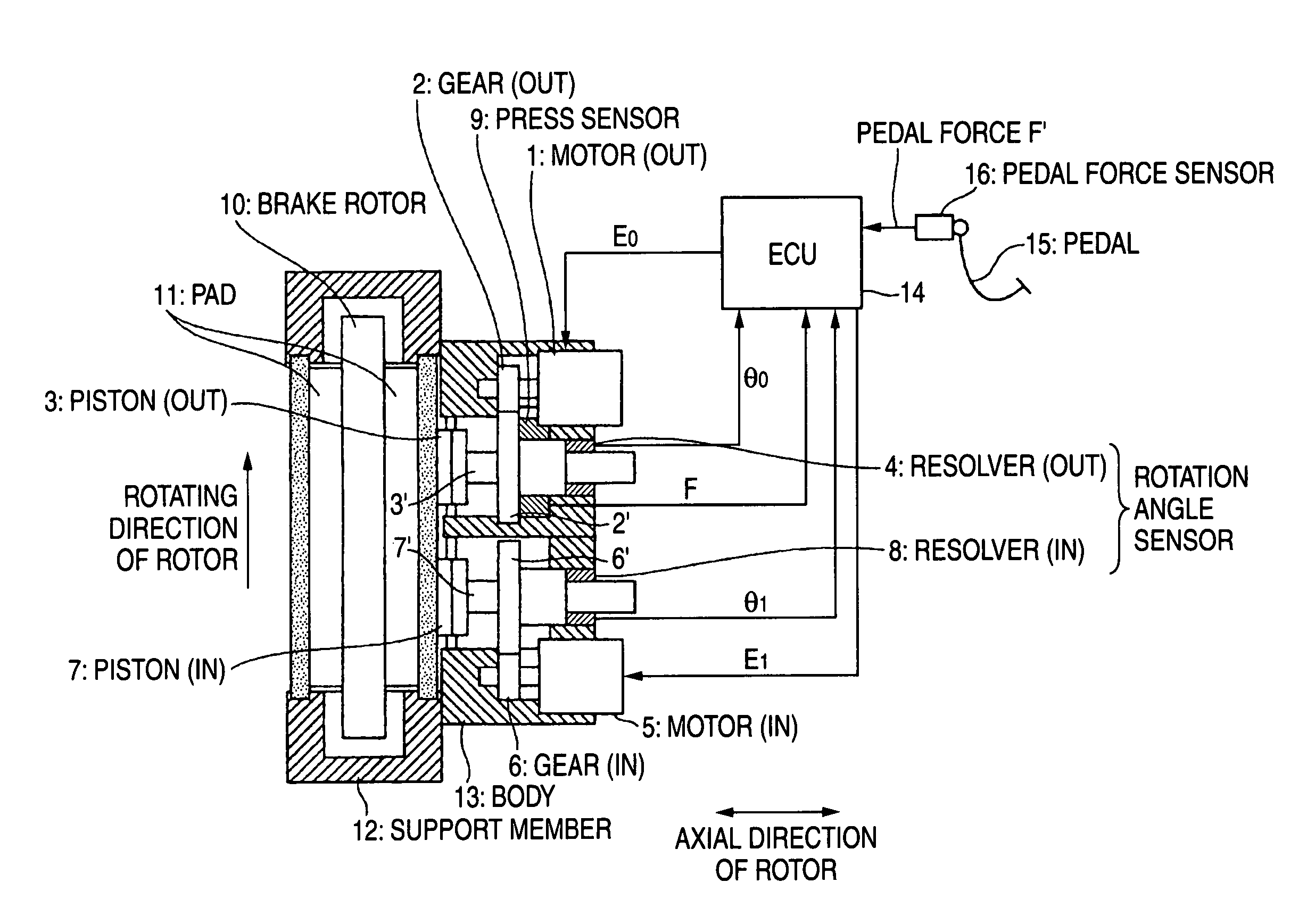
[0009]One or more embodiments of the present invention provide a method of controlling an electric brake to prevent uneven wear that can prevent the winding of the brake pad caused by the rotation of a rotor during the braking so as to suppress uneven wear.
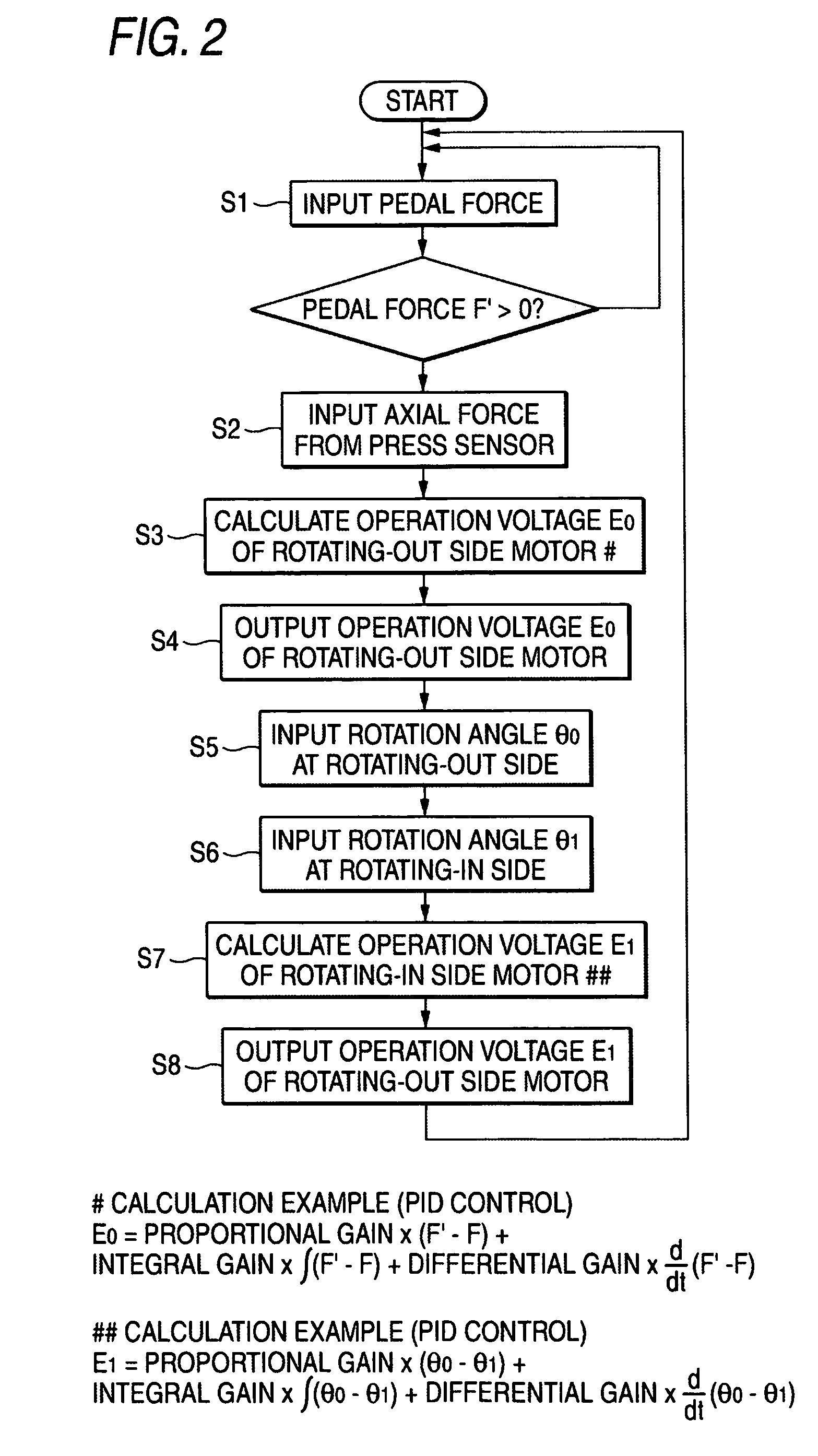
[0010]In accordance with one or more embodiments of the present invention, in the electric brake that converts rotational motions of motors fixed to a brake system into linear motions so as to move forward pistons of the brake system and presses friction members to a rotary member to apply the brake, a method of controlling an electric brake to prevent uneven wear is provided with the steps of: pressing the pistons to the friction member at two points that are positioned at a rotating-in side and a rotating-out side in the rotating direction of the rotary member; performing an axial force control for the piston on the rotating-out side; and performing a position control based on the position of the piston on the rotating-out side for the piston on the rotating-in side.
[0011]Further, in accordance with one or more embodiments of the present invention, in the electric brake that converts rotational motions of motors fixed to a brake system into linear motions so as to move forward pistons of the brake system and presses friction members to a rotary member to apply the brake, a method of controlling an electric brake to prevent uneven wear is provided with the steps of: pressing the pistons to the friction member at two points that are positioned on both sides of the rotary member at a rotating-in side and a rotating-out side in the rotating direction of the rotary member, performing axial force controls for the pistons on the rotating-out side, and performing position controls based on the positions of the pistons on the rotating-out side for the pistons on the rotating-in side. Further, in the above-mentioned methods, a sensor for detecting the position of a magnetic pole may be used in each motor to detect the positions of the pistons.
[0012]According to the embodiments of the invention, in the electric brake that converts rotational motions of motors fixed to a brake system into linear motions so as to move forward pistons of the brake system and presses friction members to a rotary member to apply the brake, a method of controlling an electric brake to prevent uneven wear is provided with the steps of: pressing the pistons to the friction member at two points that are positioned at a rotating-in side and a rotating-out side in the rotating direction of the rotary member, performing an axial force control for the piston on the rotating-out side, and performing a position control based on the position of the piston on the rotating-out side for the piston on the rotating-in side. Since the pistons are pressed to the friction member at two points that are positioned at the rotating-in side and the rotating-out side in the rotating direction of the rotary member, a pressing force is dispersed. As a result, it is possible to use a motor having a small capacity. Furthermore, since a position control based on the position of the piston on the rotating-out side is performed for the piston on the rotating-in side, it is possible to effectively prevent an excessive axial force from being applied to the friction member in accordance with a winding load generated at the rotating-in side. As a result, it is possible to prevent the uneven wear of the brake pad.
[0013]Further, in the electric brake that converts rotational motions of motors fixed to a brake system into linear motions so as to move forward pistons of the brake system and presses friction members to a rotary member to apply the brake, a method of controlling an electric brake to prevent uneven wear is provided with the steps of: pressing the pistons to the friction member at two points that are positioned on both sides of the rotary member at a rotating-in side and a rotating-out side in the rotating direction of the rotary member, performing axial force controls for the pistons on the rotating-out side, and performing position controls based on the positions of the pistons on the rotating-out side for the pistons on the rotating-in side. As a result, friction members such as brake pads come in contact with the both sides of the rotary member. Since a pressing force is further dispersed as described above even in the case of an electric brake capable of uniformly and reliably applying the brake, it is possible to use a motor having a small capacity. Furthermore, since a position control based on the position controls of the pistons on rotating-out side are performed for the pistons on the rotating-in side, it is possible to effectively prevent an excessive axial force from being applied to the brake pad in accordance with a winding load generated at the rotating-in side. As a result, it is possible to prevent the uneven wear of the brake pad.


