Sealing assembly for an ink chamber which includes self-lubricating anilox roll seal with improved blade/seal area

a technology of ink chamber and seal, which is applied in the direction of mechanical equipment, coatings, distribution equipment, etc., can solve the problems of blades, which press against anilox rolls, and the seals are exposed to mechanical stresses as well as wear, and the blades are not flexible at the opposite end of the blades wher

Inactive Publication Date: 2009-10-06
VALLEY HLDG
View PDF16 Cites 16 Cited by
  • Summary
  • Abstract
  • Description
  • Claims
  • Application Information

AI Technical Summary

Benefits of technology

[0010]It is another object of the present invention to provide a sealing assembly including doctor and sealing blade seals for an ink chamber associated with an anilox roll and doctor and sealing blades for use therewith, which permits the doctor and sealing blades to bend at the positions of the seals while still providing a good seal thereat in order to provide more even wear along the length of the blade.
[0012]It is yet another object of the present invention to provide a sealing assembly including doctor and sealing blade seals for an ink chamber associated with an anilox roll and doctor and sealing blades for use therewith, which provides a quantity of lubricant that varies in dependence upon pressure applied to the seals, thereby providing a self-lubricating seal that lubricates itself as the blades wear.
[0014]It is a still further object of the present invention to provide a sealing assembly including doctor and sealing blade seals for an ink chamber associated with an anilox roll and doctor and sealing blades for use therewith, that is easy to use and inexpensive to manufacture.
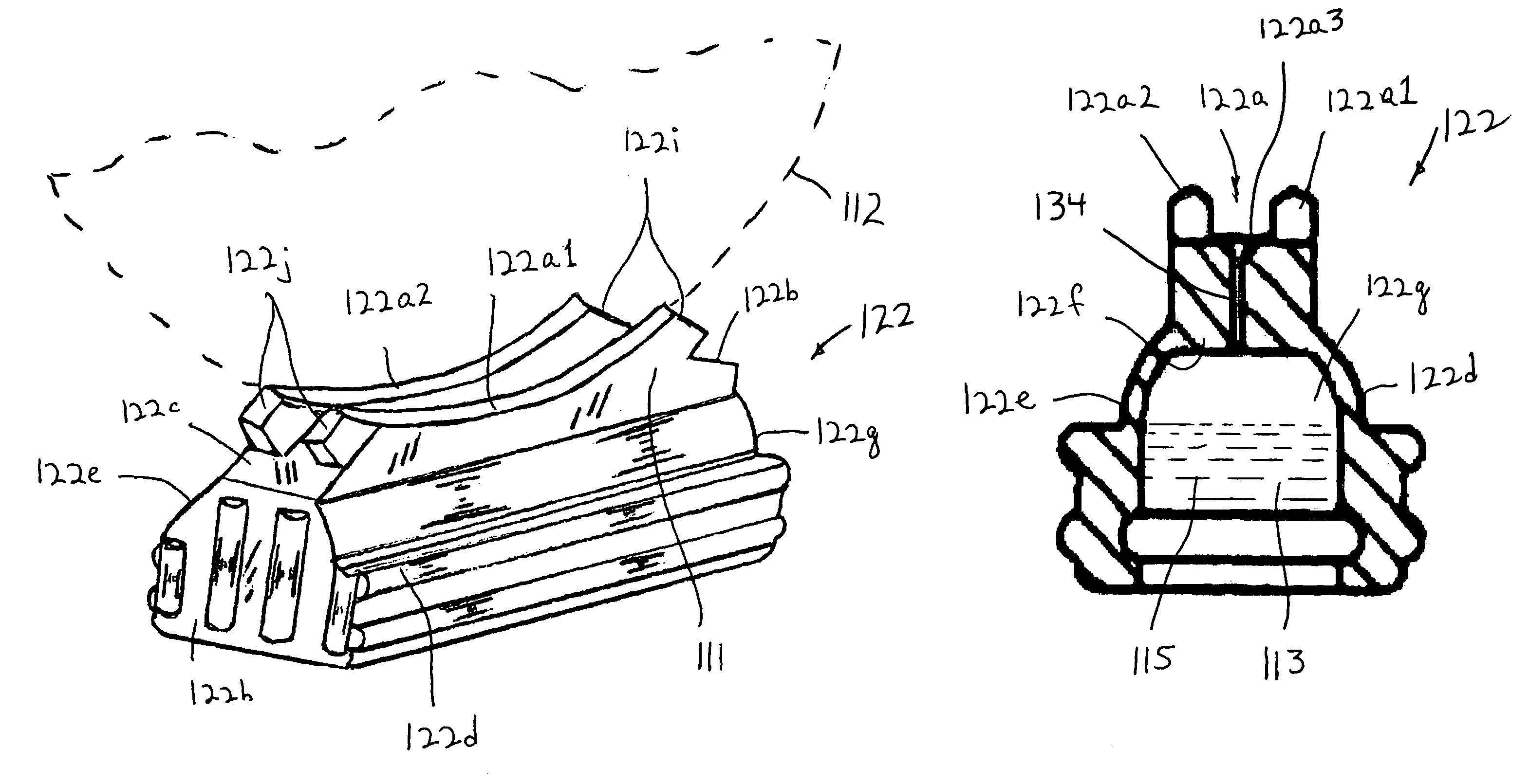
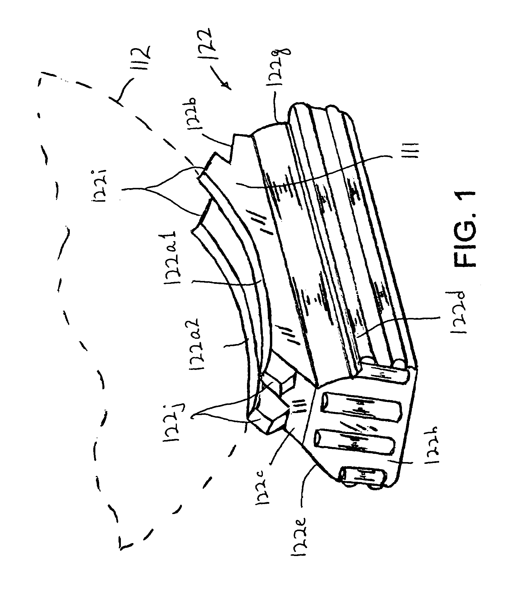
[0016]The doctor blade includes first and second opposite ends. The first seal preferably further includes a first flat upper doctor blade supporting surface at one end of the first upper wall for receiving the first end of the doctor blade thereon, and a first doctor blade engaging extension positioned above the first flat upper supporting surface. The second seal preferably further includes a second flat upper doctor blade supporting surface at one end of the second upper wall for receiving the second end of the doctor blade thereon, and a second doctor blade engaging extension positioned above the second flat upper supporting surface. In such case, the first end of the doctor blade has a first cut-out notch therein at the doctoring edge for engaging with the first doctor blade engaging extension to accurately align the first end of the doctor blade with the first seal, the first cut-out notch having a first side edge forming the first end edge in sealing engagement with the first inner facing side wall surface. In like manner, the second end of the doctor blade has a second cut-out notch therein at the doctoring edge for engaging with the second doctor blade engaging extension to accurately align the second end with the second seal, the second cut-out notch having a second side edge forming the second end edge in sealing engagement with the second inner facing side wall surface.
[0019]There is preferably a sealing blade having a sealing edge for sealing fluid on an opposite side of the fluid chamber, and opposite first and second end edges. The first end edge of the sealing blade is in sealing engagement with the first inner facing side wall surface and the second end edge of the sealing blade is in sealing engagement with the second inner facing side wall surface. The sealing blade includes opposite first and second ends. The first seal preferably further includes a first flat upper sealing blade supporting surface at an opposite end of the first upper wall for receiving the first end of the sealing blade thereon, and a first sealing blade engaging extension positioned above the first flat upper sealing blade supporting surface. The second seal preferably further includes a second flat upper sealing blade supporting surface at an opposite end of the second upper wall for receiving the second end of the sealing blade thereon, and a second sealing blade engaging extension positioned above the second flat upper sealing blade supporting surface. In such case, the first end of the sealing blade has a first cut-out notch therein for engaging with the first sealing blade engaging extension to accurately align the first end of the sealing blade with the first seal, the first cut-out notch of the sealing blade having a first side edge forming the first end edge of the sealing blade in sealing engagement with the first inner facing side wall surface. In like manner, the second end of the sealing blade preferably further has a second cut-out notch therein for engaging with the second sealing blade engaging extension to accurately align the second end of the sealing blade with the second seal, the second cut-out notch of the sealing blade having a second side edge forming the second end edge of the sealing blade in sealing engagement with the second inner facing side wall surface.
[0022]The doctor blade includes first and second opposite ends; the first seal includes a first flat upper doctor blade supporting surface at one end of the first upper wall for receiving the first end of the doctor blade thereon, and a first doctor blade engaging extension positioned above the first flat upper doctor blade supporting surface; the second seal includes a second flat upper doctor blade supporting surface at one end of the second upper wall for receiving the second end of the doctor blade thereon, a second doctor blade engaging extension positioned above the second flat upper doctor blade supporting surface; the first end of the doctor blade has a first cut-out notch therein at the doctoring edge; and the second end of the doctor blade has a second cut-out notch therein at the doctoring edge. The method further includes the steps of engaging the first cut-out notch with the first doctor blade engaging extension to accurately align the first end of the doctor blade with the first seal such that a first side edge of the first cut-out notch which forms the first end edge is in sealing engagement with the first inner facing side wall surface. The method also includes the step of engaging the second cut-out notch with the second doctor blade engaging extension to accurately align the second end of the doctor blade with the second seal such that a second side edge of the second cut-out notch which forms the second end edge is in sealing engagement with the second inner facing side wall surface.

Problems solved by technology

As a result, each seal is therefore exposed to mechanical stresses as well as wear.
Further, during the printing operation, the blades, which press against the anilox roll, also wear.
As a result, there is not much flexibility at the opposite ends of the blades where they are held by the chamber seals.
Because there is more force by the seals on each blade, that is, at the ends of the blades where they are held, the ends of the blades are less capable of flexing or bending at these points.
As a result, there is uneven wear on the ends of the blades adjacent the seals, which tends to cause more wear and more leakage of ink at the ends of the anilox roll.
Further, ink tends to ride under the blade, that is, between the blade and the flat supporting area of the seal, causing the blade to lift up away from the seal, thereby resulting in still more leakage.
Thus, the place where the seal, anilox roll and blades join, is particularly susceptible to leakage.
However, if a seal is not lubricated, the dried ink will wear the blades faster in the seal areas.
In either case, the areas where the anilox roll, blades and seals join are susceptible to leakage because of geometric changes.

Method used


Image

  • Sealing assembly for an ink chamber which includes self-lubricating anilox roll seal with improved blade/seal area
  • Sealing assembly for an ink chamber which includes self-lubricating anilox roll seal with improved blade/seal area
  • Sealing assembly for an ink chamber which includes self-lubricating anilox roll seal with improved blade/seal area

Examples


Embodiment Construction

[0044]Referring to the drawings in detail, and initially to FIG. 11 thereof, there is shown a conventional doctor and sealing blade sealing assembly 10. Conventionally, in printing machines, such as flexographic printing machines, an ink transfer or anilox roll 12 transfers ink to an adjacent plate roll (not shown) for printing. Ink is supplied to anilox roll 12 from an ink chamber 14 defined by a chamber housing 16 which is adjacent to and may partially surround anilox roll 12. Anilox roll 12 rotates in the direction of arrow 12a.

[0045]In order to prevent the escape of ink from ink chamber 14, while ensuring that the ink enters the cells in anilox roll 12 and has a predetermined volume on anilox roll12, sealing and doctor blades 18 and 20 are provided at the entry and exit positions of anilox roll 12 relative to ink chamber 14. Blades 18 and 20 are fixed to chamber housing 16 by an blade holder (not shown) so that blades 18 and 20 overhang chamber housing 16 and contact anilox rol...


PUM


Abstract

A sealing assembly for an ink chamber associated with an anilox roll, includes a doctor blade having a doctoring edge, with each end having a notch at the doctoring edge, and first and second seals adapted to seal ends of the ink chamber. Each seal includes a peripheral supporting wall, an upper wall thereon including an upper concave surface for engaging an outer surface of the anilox roll, a flat upper supporting surface at opposite ends of the upper wall on which ends of the doctor blade seat, and an extension above the flat upper supporting surface for engaging within the notch at the end of the doctor blade to permit the doctor blade to bend thereat. A lubricant chamber is defined therein and the upper wall includes an opening through which the lubricant is forced out of the lubricant chamber due to external pressure.

Description

BACKGROUND OF THE INVENTION[0001]The present invention relates to a sealing assembly including self-lubricating doctor and sealing blade seals for an ink chamber associated with an anilox roll and doctor and sealing blades for use therewith, and which permits the doctor and sealing blades to bend at their ends to provide an improved blade / seal area.[0002]Conventionally, in printing machines, such as flexographic printing machines, an ink transfer or anilox roll transfers ink to an adjacent plate roll for printing. Ink is supplied to the anilox roll from an ink chamber defined by a chamber housing which partially surrounds the anilox roll. Specifically, ink is supplied through an ink supply tube and then through an ink supply line in the chamber housing, into the ink chamber. In like manner, ink is removed from the ink chamber through an ink return line in the chamber housing and then through an ink return tube.[0003]In order to prevent the escape of ink from the chamber, while ensur...

Claims


Application Information

Patent Timeline
Patent Type & Authority Patents(United States)
IPC IPC(8): B05C3/00
CPCB41F31/027B41F9/065
Inventor VAN DENEND, MARK E.
Owner VALLEY HLDG
Why Eureka
Try Eureka