Electric brake

a technology of brakes and brake rotors, applied in the direction of brake systems, brake components, transportation and packaging, etc., can solve the problems of insufficient to reliably prevent uneven wear of brake pads, and even wear of brake pads or brake rotors, so as to prevent uneven wear and suppress uneven wear

Inactive Publication Date: 2007-03-22
AKEBONO BRAKE IND CO LTD
View PDF9 Cites 16 Cited by
  • Summary
  • Abstract
  • Description
  • Claims
  • Application Information

AI Technical Summary

Benefits of technology

[0009] One or more embodiments of the present invention provide a method of controlling an electric brake to prevent uneven wear that can prevent the winding of the brake pad caused by the rotation of a rotor during the braking so as to suppress uneven wear.
[0010] In accordance with one or more embodiments of the present invention, in the electric brake that converts rotational motions of motors fixed to a brake system into linear motions so as to move forward pistons of the brake system and presses friction members to a rotary member to apply the brake, a method of controlling an electric brake to prevent uneven wear is provided with the steps of: pressing the pistons to the friction member at two points that are positioned at a rotating-in side and a rotating-out side in the rotating direction of the rotary member; performing an axial force control for the piston on the rotating-out side; and performing a position control based on the position of the piston on the rotating-out side for the piston on the rotating-in side.
[0011] Further, in accordance with one or more embodiments of the present invention, in the electric brake that converts rotational motions of motors fixed to a brake system into linear motions so as to move forward pistons of the brake system and presses friction members to a rotary member to apply the brake, a method of controlling an electric brake to prevent uneven wear is provided with the steps of: pressing the pistons to the friction member at two points that are positioned on both sides of the rotary member at a rotating-in side and a rotating-out side in the rotating direction of the rotary member, performing axial force controls for the pistons on the rotating-out side, and performing position controls based on the positions of the pistons on the rotating-out side for the pistons on the rotating-in side. Further, in the above-mentioned methods, a sensor for detecting the position of a magnetic pole may be used in each motor to detect the positions of the pistons.
[0012] According to the embodiments of the invention, in the electric brake that converts rotational motions of motors fixed to a brake system into linear motions so as to move forward pistons of the brake system and presses friction members to a rotary member to apply the brake, a method of controlling an electric brake to prevent uneven wear is provided with the steps of: pressing the pistons to the friction member at two points that are positioned at a rotating-in side and a rotating-out side in the rotating direction of the rotary member, performing an axial force control for the piston on the rotating-out side, and performing a position control based on the position of the piston on the rotating-out side for the piston on the rotating-in side. Since the pistons are pressed to the friction member at two points that are positioned at the rotating-in side and the rotating-out side in the rotating direction of the rotary member, a pressing force is dispersed. As a result, it is possible to use a motor having a small capacity. Furthermore, since a position control based on the position of the piston on the rotating-out side is performed for the piston on the rotating-in side, it is possible to effectively prevent an excessive axial force from being applied to the friction member in accordance with a winding load generated at the rotating-in side. As a result, it is possible to prevent the uneven wear of the brake pad.
[0013] Further, in the electric brake that converts rotational motions of motors fixed to a brake system into linear motions so as to move forward pistons of the brake system and presses friction members to a rotary member to apply the brake, a method of controlling an electric brake to prevent uneven wear is provided with the steps of: pressing the pistons to the friction member at two points that are positioned on both sides of the rotary member at a rotating-in side and a rotating-out side in the rotating direction of the rotary member, performing axial force controls for the pistons on the rotating-out side, and performing position controls based on the positions of the pistons on the rotating-out side for the pistons on the rotating-in side. As a result, friction members such as brake pads come in contact with the both sides of the rotary member. Since a pressing force is further dispersed as described above even in the case of an electric brake capable of uniformly and reliably applying the brake, it is possible to use a motor having a small capacity. Furthermore, since a position control based on the position controls of the pistons on rotating-out side are performed for the pistons on the rotating-in side, it is possible to effectively prevent an excessive axial force from being applied to the brake pad in accordance with a winding load generated at the rotating-in side. As a result, it is possible to prevent the uneven wear of the brake pad.

Problems solved by technology

As a result, since the brake pad is not uniformly contacted with the rotary member such as a brake rotor, there has been an undesirable possibility that an uneven wear occurs in the brake pad or the brake rotor.
For this reason, it has been still insufficient to reliably prevent the uneven wear of the brake pad.

Method used


Image

  • Electric brake
  • Electric brake
  • Electric brake

Examples


Embodiment Construction

[0020] Exemplary embodiments of the invention will be described with reference to the accompanying drawings.

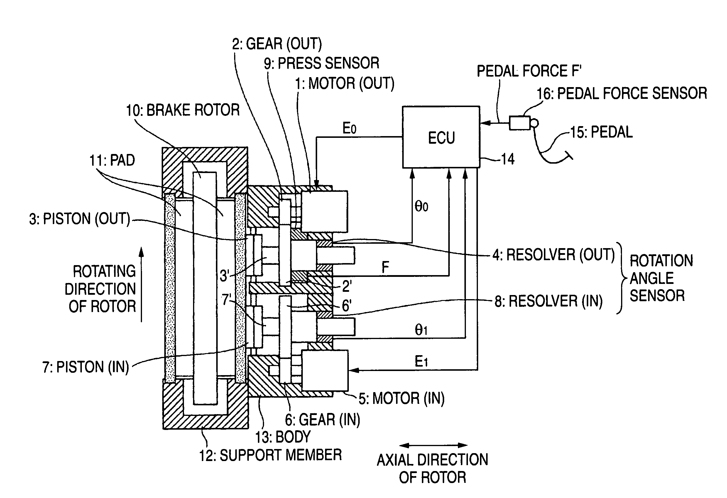
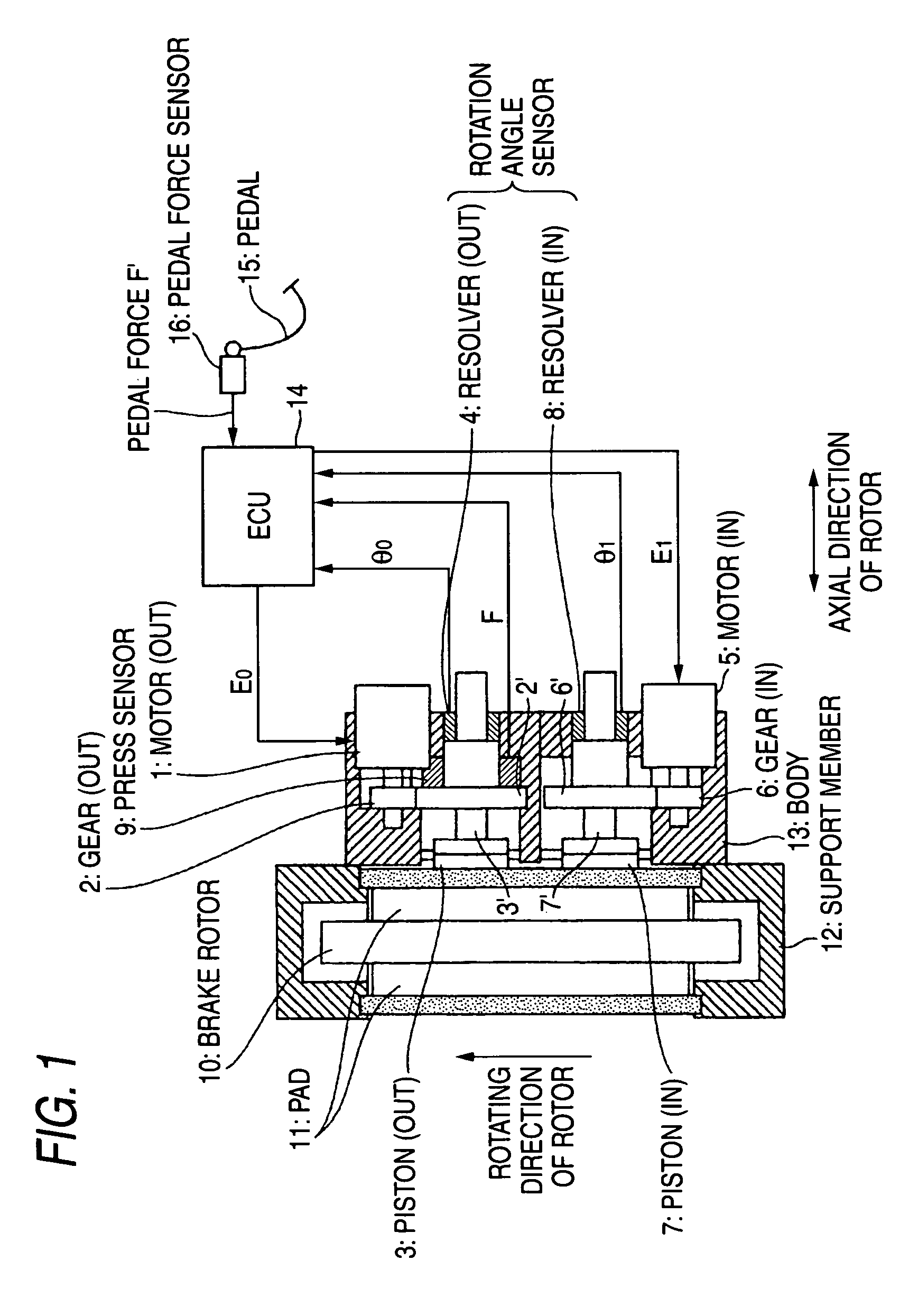
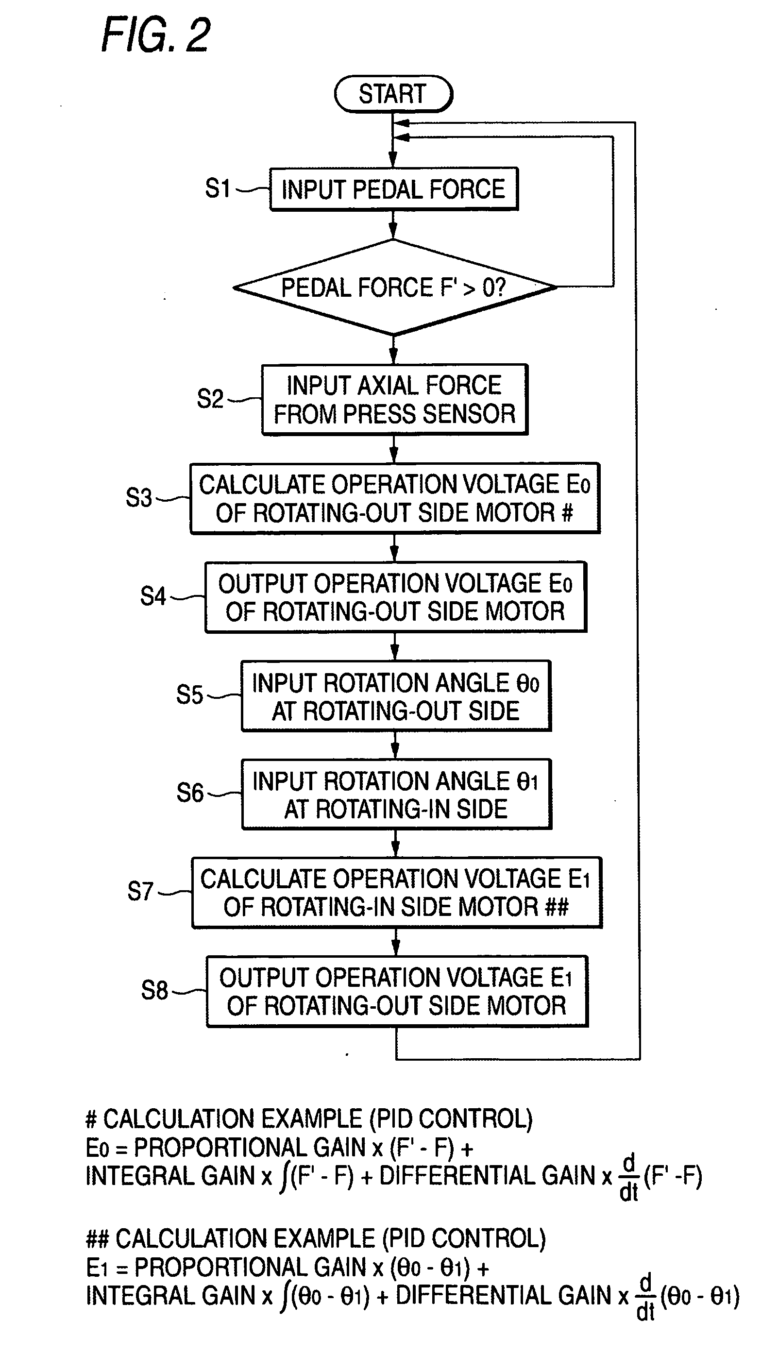
[0021]FIG. 1 is a view showing the entire configuration of an electric brake according to a first exemplary embodiment of the invention, and FIG. 2 is a flow chart of a control method of the electric brake according to the first exemplary embodiment. FIG. 3 is a view showing the partial configuration of an electric brake according to the second embodiments of the invention.

[0022] In the electric brake according to the first exemplary embodiment, as shown in FIG. 1, the electric brake converts rotational motions of motors fixed to a brake system into linear motions so as to move forward pistons of the brake system so that friction members 11 are pressed to a rotary member 10 to apply the brake. The pistons 3 and 7 are pressed to the friction member 11 at two points that are positioned at a rotating-in side and a rotating-out side in a rotating direction of the rotary member 1...


PUM


Abstract

Pistons 3 and 7 are pressed to a friction member 11 at two points that are positioned at a rotating-in side and a rotating-out side in a rotating direction of a brake rotor 10. An axial force control is performed for the piston 3 on the rotating-out side, and a position control based on the position of the piston 3 on the rotating-out side is performed for the piston 7 on the rotating-in side.

Description

[0001] This application claims foreign priority from Japanese Patent Application No. 2005-273498, filed on Sep. 21, 2005, the entire contents of which are hereby incorporated by reference. BACKGROUND OF THE INVENTION [0002] 1. Field of the Invention [0003] The present invention relates to an electric brake that converts rotational motions of motors fixed to a brake system into linear motions so as to move forward pistons of the brake system and to press friction members to a rotary member to apply the brake. [0004] 2. Related Art [0005] An internal combustion engine, which uses gasoline or the like as fuel, has been used as a power source in a vehicle such as an automobile to obtain high power. However, an electric vehicle or a hybrid electric vehicle has been used in recent years in terms of environmental measures or fuel efficiency, and an electric motor has been used as a main power source or an auxiliary power source. Accordingly, an electric brake has also been commonly used, i...

Claims


Application Information

Patent Timeline
Patent Type & Authority Applications(United States)
IPC IPC(8): F16D66/00F16D65/18
CPCB60T13/746F16D65/18F16D2121/24F16D2066/006F16D2066/003
Inventor TAKAHASHI, HIDEAKITAKAHASHI, KIMIO
Owner AKEBONO BRAKE IND CO LTD
Why Eureka
Try Eureka