Disc brake caliper

a disc brake and caliper technology, applied in the direction of axially engaging brakes, brake types, braking elements, etc., can solve the problems of not being as stiff as desirable, having an opposing piston caliper such as those described above, and complicating the manufacture and assembly process, so as to reduce the cost of the caliper, lessen the extent of tapered wear, and wear more evenly

a disc brake and caliper technology, applied in the direction of axially engaging brakes, brake types, braking elements, etc., can solve the problems of not being as stiff as desirable, having an opposing piston caliper such as those described above, and complicating the manufacture and assembly process, so as to reduce the cost of the caliper, lessen the extent of tapered wear, and wear more evenly

US20080264738A1Inactive Publication Date: 2008-10-30PBR AUSTRALIA PTY LTD

Image

  • Disc brake caliper
  • Disc brake caliper
  • Disc brake caliper

Examples


Embodiment Construction

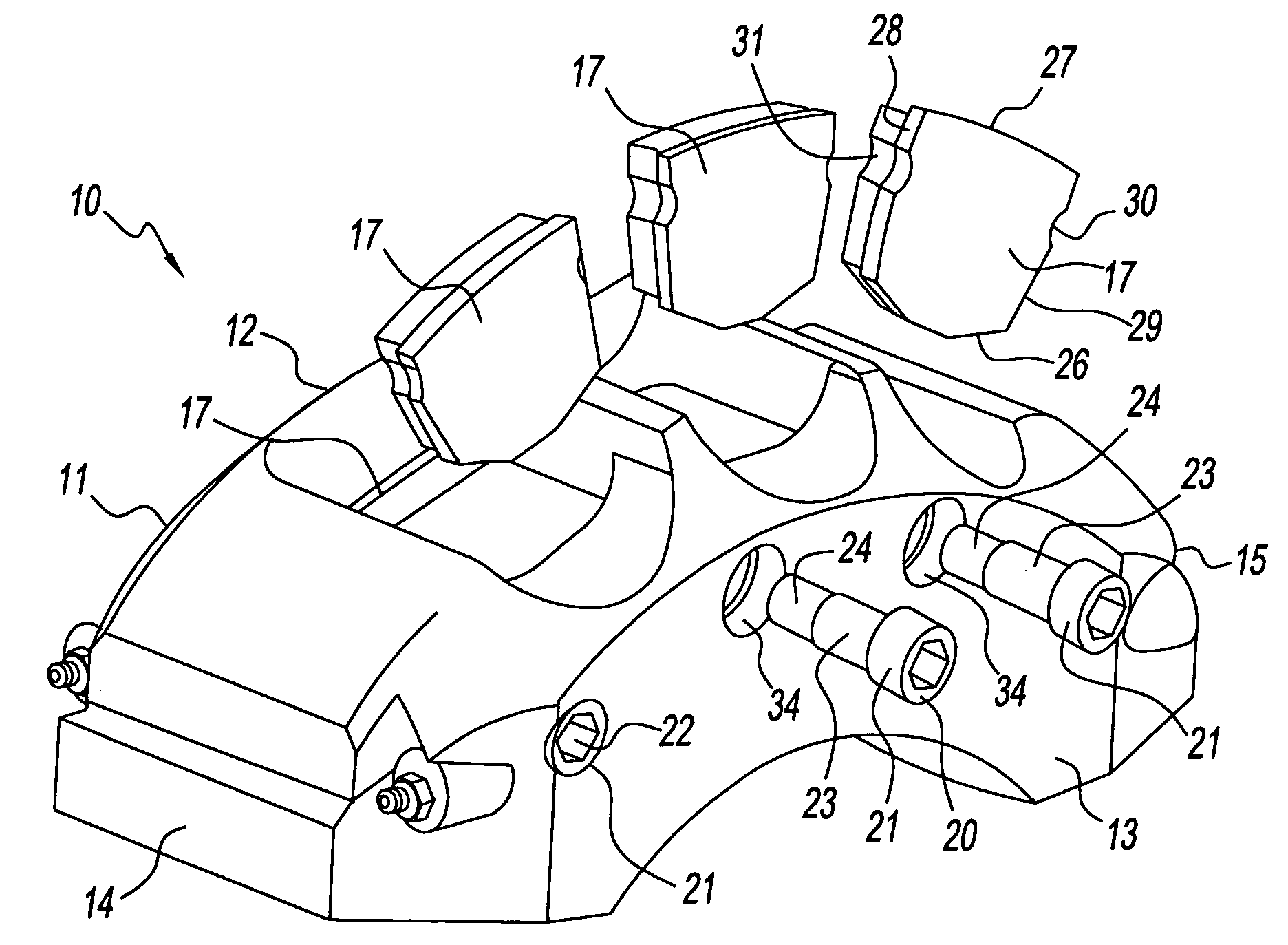
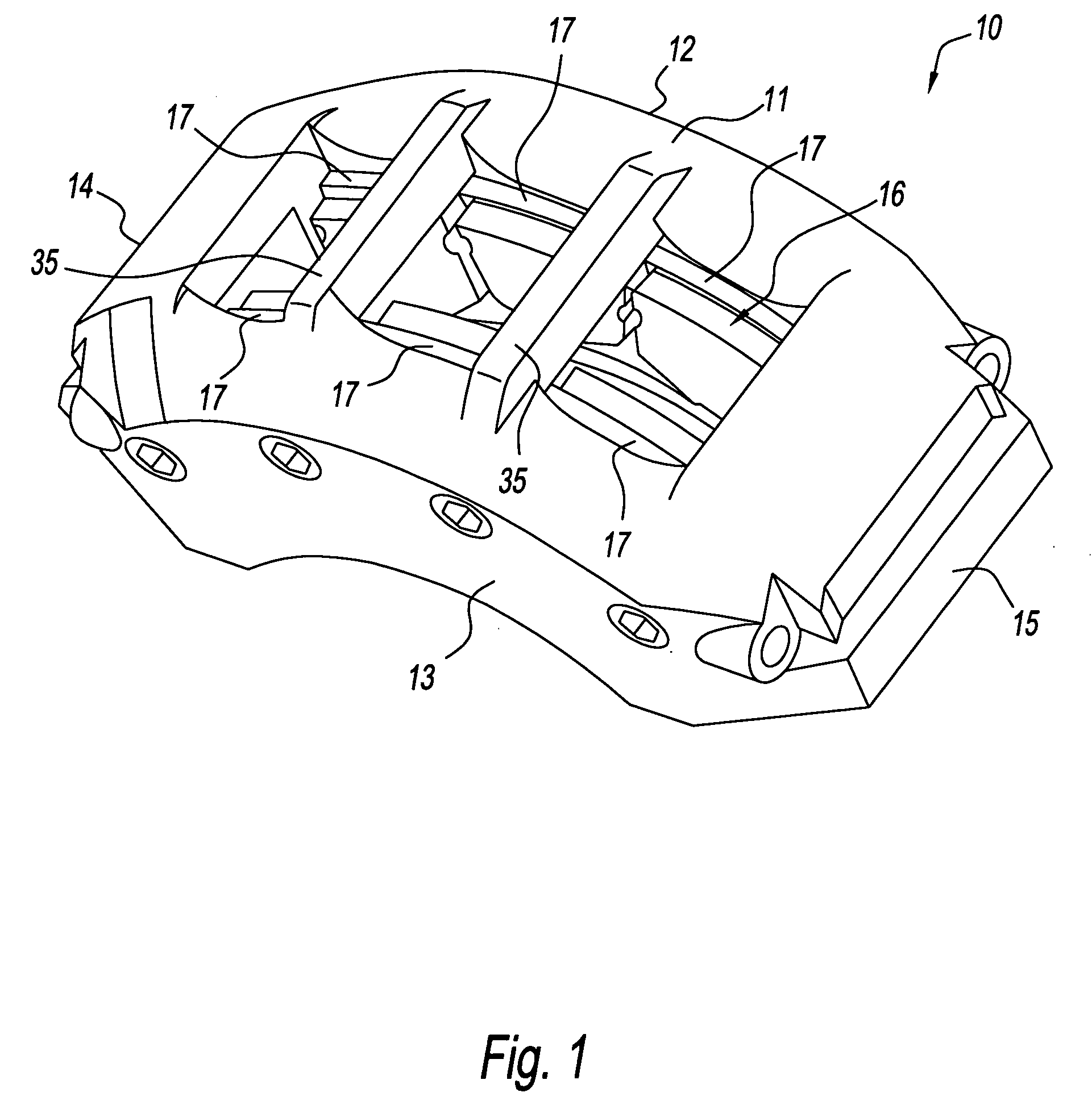
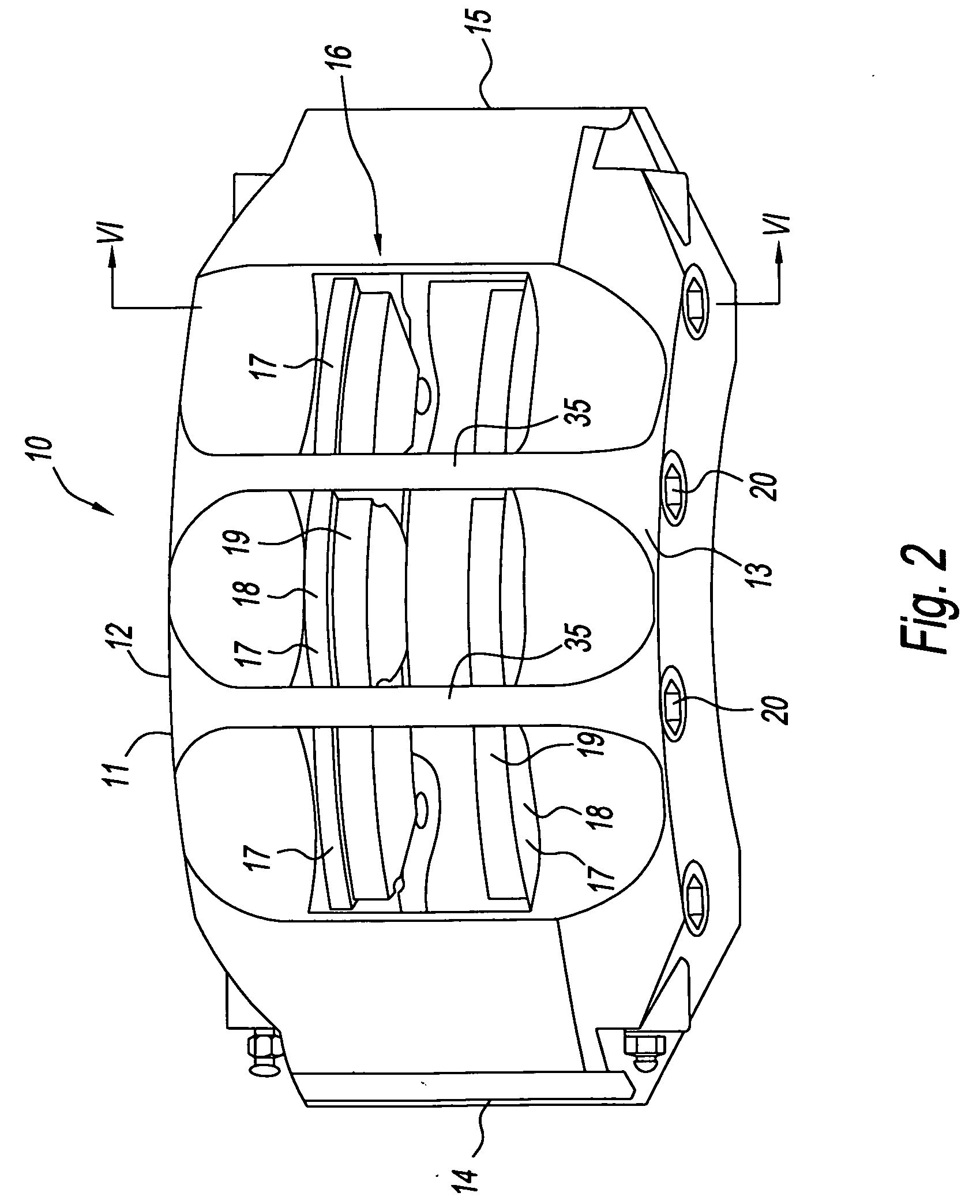
[0038]FIG. 1 shows a disc brake caliper according to the invention as described above. The disc brake caliper 10 includes a housing 11 defining a pair of parallel side walls 12 and 13 and a pair of end walls 14 and 15 which extend transversely to the side walls 12 and 13 and are connected thereto. The housing 11 has a generally rectangular configuration in plan view and typically would be cast in a suitable metal such as iron or aluminum. The housing would then be machined as necessary.

[0039]The side walls 12 and 13 and the end walls 14 and 15 define an opening 16 in the housing 11. The opening 16 is of generally rectangular configuration and the internal surfaces of the opening defined by the side walls 12 and 13 are machined for mounting of a plurality of brake shoes 17 there against. In FIG. 1, three brake shoes 17 are mounted to each side wall 12 and 13 and each brake shoe consists of a metal backing plate 18 and a friction lining 19. While these parts of the brake shoes can be ...


PUM


Abstract

An opposed piston disc brake caliper has a caliper housing arranged for mounting brake shoes on each of opposite sides of a rotor. The rotor in use is disposed between the brake shoes with each brake shoe having a backing plate and a friction lining applied to the backing plate. The caliper housing has side walls extending generally in a plane parallel to a plane of the rotor and on opposite sides of the plane of the rotor which accommodate a piston. The caliper housing has mounting members for engagement with each of the side edges of each backing plate between the radially inner edge and the radially outer edge of the friction lining. The engagement is such as to substantially limit movement of each brake shoe other than in a direction toward or away from the rotor with at least one of the mounting members being removable from the caliper housing to facilitate removal of the brake shoe from the caliper housing.

Description

CROSS REFERENCE TO RELATED PATENT APPLICATIONS[0001]The present application is a continuation of U.S. patent application Ser. No. 10 / 921,631 filed Aug. 19, 2004 entitled “Disc Brake Caliper,” now pending, which claims priority of PCT International Application No. PCT / AU03 / 00224 filed on Feb. 21, 2003 and Australian Patent Application No. PS 0668 filed on Feb. 21, 2002. The aforementioned applications are hereby incorporated herein by reference in their entirety.BACKGROUND OF THE INVENTION[0002]1. Field of the Invention[0003]The present invention relates to disc brake calipers and to improvements thereof. The present invention has particular relevance to disc brake calipers of the kind which include opposed pistons and it will therefore be convenient to describe the invention in relation to that type of caliper. It is to be appreciated however, that the invention could apply to calipers not of the opposed piston kind.[0004]2. Description of Related Art[0005]Opposed piston calipers ha...

Claims


Application Information

Patent Timeline
30 Oct 2008
Publication
US20080264738A1
IPC
F16D55/228; F16D65/092; F16D65/095
CPC
F16D55/228; F16D65/092; F16D65/095; F16D2055/002; F16D2055/007; F16D2055/0091
Inventors
REEVES, KEITH CLARKSON