
Robot integrated joint unit and foot type robot applying same

A technology of robots and joints, applied in manipulators, motor vehicles, program-controlled manipulators, etc., can solve the problems of increasing the complexity and space size of joints, affecting the safety and aesthetics of the robot structure, and uneven wear of the teeth of the reducer. Uneven wear, beautiful structure, balanced wear effect

Pending Publication Date: 2019-06-28
HZ UNITREE TECHNOLOGY CO LTD
View PDF0 Cites 16 Cited by
  • Summary
  • Abstract
  • Description
  • Claims
  • Application Information

AI Technical Summary

Problems solved by technology

[0004] There are two main ways to arrange the existing lines: one is to use non-hollow wiring, and the wires are directly hung outside the joints of the robot, but this affects the safety and aesthetics of the robot structure, and the wires are easily damaged. , which will affect the range of motion of the joint; another way is to use hollow wiring, but the motor component and the joint connecting rod need to reserve special threading holes and cable placement mechanisms, which increases the complexity and space of the joint. The movement of the wire will cause wear and fatigue damage, affecting the service life of the wire
[0005] Furthermore, due to the complex and changeable terrain of the ground or the impact interference from the outside world, when the driving torque of the robot joint motor is greater than the maximum torque that the joint reducer can bear or the maximum torque transmitted to the reducer from the outside through the output shaft of the reducer is greater than When the maximum torque that the joint reducer can withstand, the reducer of the robot joint will be in an overload working state, which will cause damage to the joint parts such as the reducer gear
In addition, since the joints of the robot work in the reciprocating mode for a long time under many working conditions, and need to bear the impact load from the ground or the external environment, the meshing tooth surface of each tooth of the reducer will have serious uneven wear.

Method used


Image

  • Robot integrated joint unit and foot type robot applying same
  • Robot integrated joint unit and foot type robot applying same
  • Robot integrated joint unit and foot type robot applying same

Examples


Embodiment Construction

[0034] In order to make the object, technical solution and advantages of the present invention clearer, the present invention will be further described in detail below in conjunction with the accompanying drawings and embodiments. It should be understood that the specific embodiments described here are only used to explain the present invention, not to limit the present invention.

[0035] On the contrary, the invention covers any alternatives, modifications, equivalent methods and schemes within the spirit and scope of the invention as defined by the claims. Further, in order to make the public have a better understanding of the present invention, some specific details are described in detail in the detailed description of the present invention below. The present invention can be fully understood by those skilled in the art without the description of these detailed parts.

[0036] It should be noted that when two elements are referred to as being "fixedly connected", the two...


PUM


Abstract

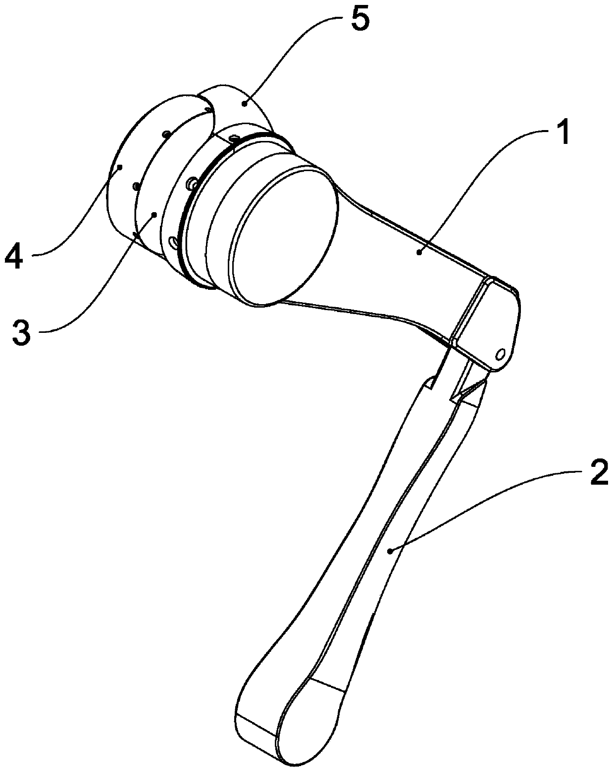
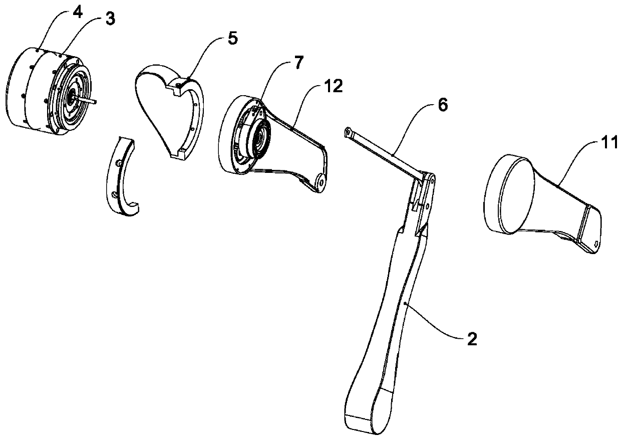
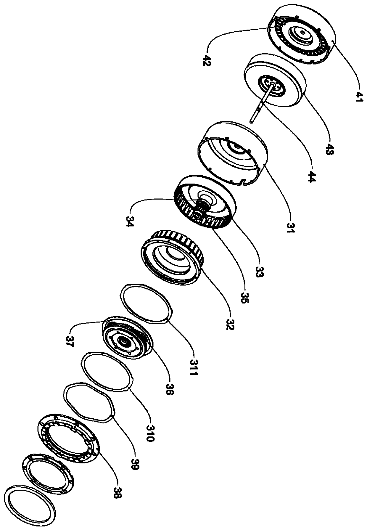
The invention discloses a robot integrated joint unit and a foot type robot applying the same, and belongs to the technical field of robot joints. An existing double-joint line arrangement mode influences structure safety and attractiveness of a robot, a wire is easily damaged, and the service life of the wire is influenced. The robot comprises a first motor, a speed reducer assembly, a second motor assembly, a second speed reducer assembly and a first output connecting rod. Double motors of double joints are located on the same side of the joints, and the situation that a motor power cable needs to pass through the joints is avoided so that the fatigue damage of the motor power cable can be effectively relieved, and the service life of the motor cable wire can be prolonged. The motor assembly and a joint connecting rod do not need to reserve a special threading hole and a cable arrangement mechanism, so that the structure is more reliable; the integration degree of the double-joint unit is further improved, the axial size of the joint unit is reduced, and the structure is more attractive.

Description

technical field [0001] The invention relates to a robot integrated joint unit and a legged robot using the same, belonging to the technical field of robot joints. Background technique [0002] At present, the power unit used for the robot generally adopts the structure of independent joint units connected in series or in parallel. Especially in the field of legged robots, each leg of the robot is usually a structure in which independent joint units are connected in series. [0003] For the double-joint unit with compact structure, especially for legged robots, the two motors of the existing double-joint unit are arranged on both sides of the rotary joint. In order to ensure the normal operation of the double-joint motors, the wiring layout must be considered. [0004] There are two main ways to arrange the existing lines: one is to use non-hollow wiring, and the wires are directly hung outside the joints of the robot, but this affects the safety and aesthetics of the robot ...

Claims


Application Information

Patent Timeline
Patent Type & Authority Applications(China)
IPC IPC(8): B62D57/032
CPCB62D57/032B25J17/00B25J9/102B25J19/0045B25J19/0054B25J13/088B25J17/0233
Inventor 王兴兴杨知雨
Owner HZ UNITREE TECHNOLOGY CO LTD
Learn More