Push type driving belt

a driving belt and push-type technology, applied in the direction of driving belts, belts/chains/gearings, v-belts, etc., can solve the problems of uneven application of load derived from a tension of rings or the like to the saddle face of elements, affecting and inevitably occurring slippage between singly layered rings. to achieve the effect of improving the power transmission efficiency of driving belts

Inactive Publication Date: 2011-09-29
TOYOTA JIDOSHA KK
View PDF11 Cites 13 Cited by
  • Summary
  • Abstract
  • Description
  • Claims
  • Application Information

AI Technical Summary

Benefits of technology

[0014]The present invention has been conceived noting the technical problems thus far described, and its object is to provide a push-type driving belt, which is capable of preventing uneven wear of a ring and deterioration in durability of the belt, by preventing a transmission loss resulting from a slippage of the ring, and by positioning the ring accurately with respect to an element.
[0019]Thus, according to the present invention, the driving belt is formed by fastening the element by the ring, and the ring is a monolithic annular member which is formed into a single layer in its thickness direction and which is formed of elastic material the hardness thereof is lower than that of the element. Therefore, transmission loss resulting from an internal slippage of the ring will not occur even if the driving belt is driven, unlike the conventional layered ring formed by overlapping a plurality of thin belt members. For this reason, power transmission efficiency of the driving belt can be improved.
[0020]As described, according to the present invention, the inclined faces are formed individually on the side faces of the ring. Therefore, the cross section of the ring is a laterally symmetrical trapezoidal shape. On the other hand, the contact faces or the contact curved faces to be contacted with the inclined faces of the ring are formed individually on the inner side walls of the recess of the element holding the ring therein. Alternatively, the inclined faces are formed individually on the inner side walls of the recess of the element. Therefore, the recess is formed into a laterally symmetrical trapezoidal shape. On the other hand, the contact faces or the contact curved faces to be contacted with the inclined faces of the recess is formed individually on the side faces of the ring. Therefore, according to the present invention, the ring held in the recess of the element is positioned at the width center of the recess by the inclined faces. In addition, the contact area between the inclined face and the contact face or the contact curved face is smaller than the area of the inclined face. Therefore, the ring can be prevented from being contacted with the inner wall of the recess unevenly only at one of the side faces thereof, that is, a load will not be applied to only one of the side faces of the ring. For this reason, a frictional loss at the contact portion between the side face of the ring and the inner wall of the element can be prevented or avoided, and the ring will not be worn only at one of the side faces thereof.
[0021]As also described, according to the present invention, the inclined faces are formed in a manner to widen the distance therebetween from the diametrically outer circumferential side of the belt toward the diametrically inner circumferential side of the belt. That is, the opening width of the recess is narrower than the width of the recess at the diametrically inner circumferential side. Therefore, the ring can be prevented from being detached from the element so that the driving belt can be formed firmly by fastening the elements by the ring.
[0022]In addition, according to the present invention, even if the ring is deformed elastically to be expanded widthwise by a load resulting from driving the belt, the expanded portion of the ring is housed in the relief area formed on the inner wall of the recess. Therefore, the contact load between the side face of the ring and the inner wall of the recess will not be increased even if the ring is deformed by the load. For this reason, a frictional loss at the contact portion between the side face of the ring and the inner wall of the element can be prevented or avoided, and the ring will not be worn only at one of the side faces thereof.

Problems solved by technology

However, in case of using the metal ring assembly of Japanese patent No. 3406283 or the layered ring 100 in the driving belt, a slippage between the singly layered rings will occur inevitably when the driving belt is driven to transmit the power.
Therefore, power transmission efficiency of the driving belt has to be degraded by such internal slippage of the layered ring.
Therefore, in this case, a load derived from a tension of the ring or the like may be applied to the saddle face of the element unevenly.
For example, in case of fastening the elements of Japanese patent No. 3406283 having the crowning on the saddle face using the ring made of rubber or resin whose hardness is relatively low, a frictional force acting between the saddle face of the element and the innermost surface of the ring has to be unstable.
Therefore, the ring may not be positioned in the center of the element accurately.

Method used


Image

  • Push type driving belt
  • Push type driving belt
  • Push type driving belt

Examples


Embodiment Construction

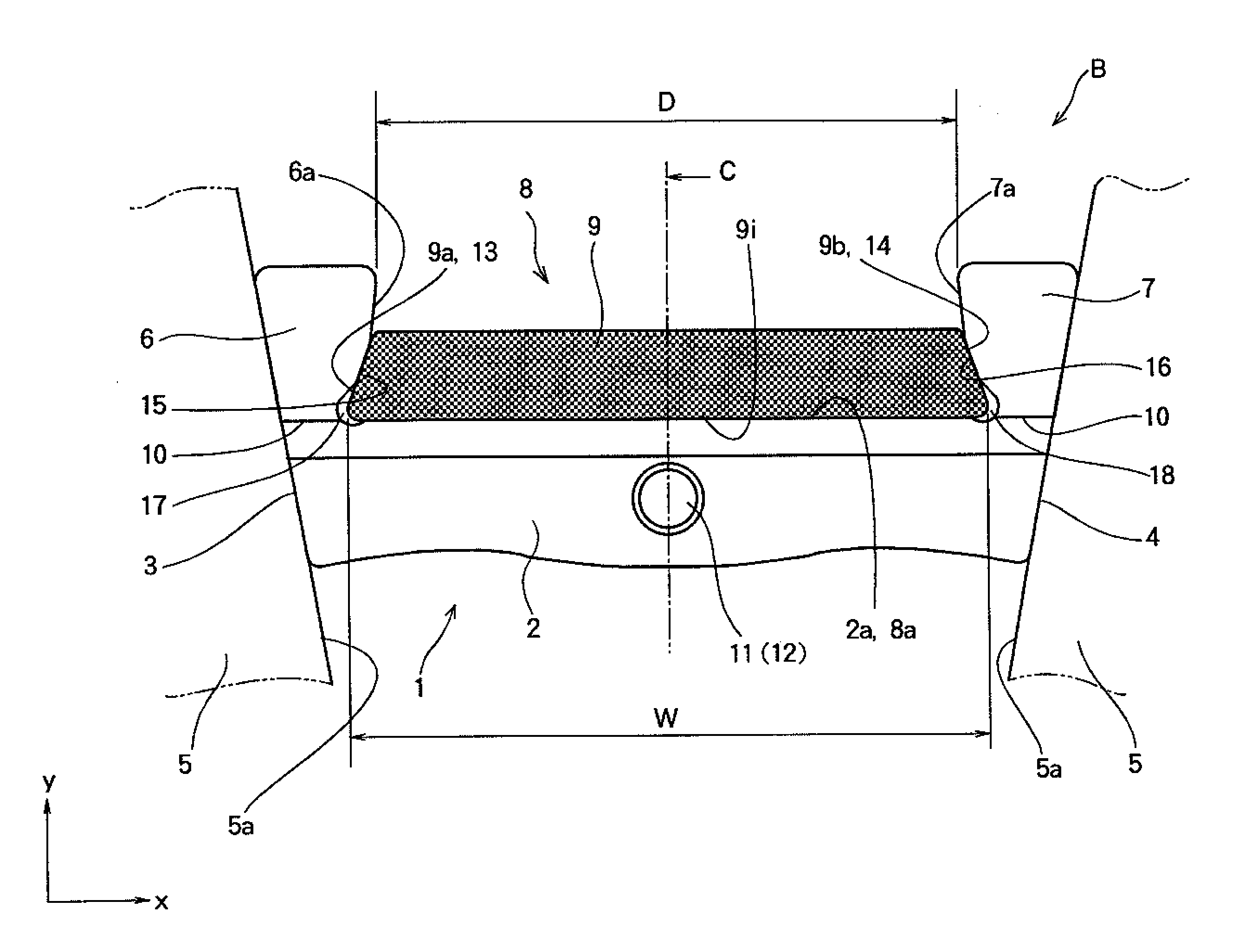
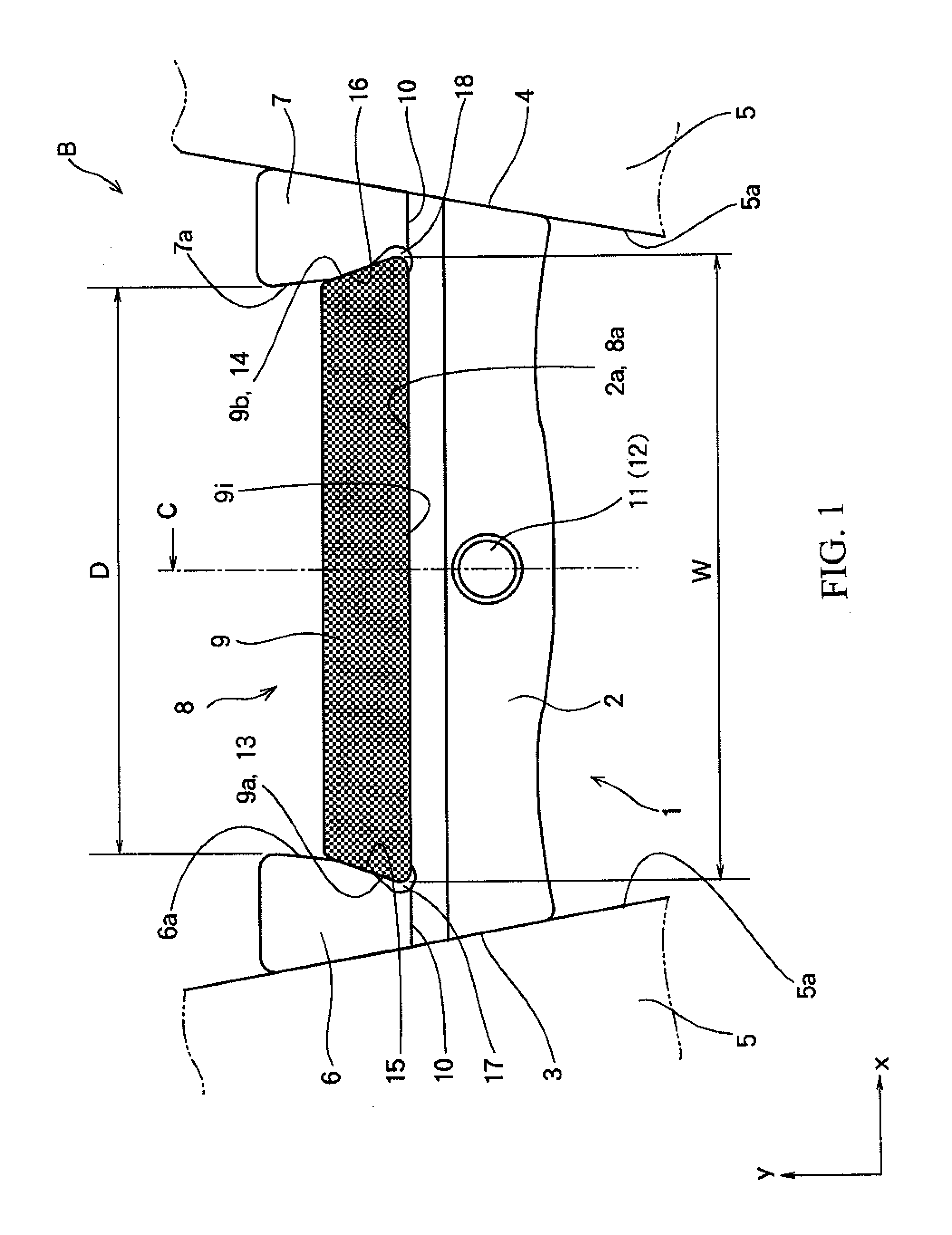
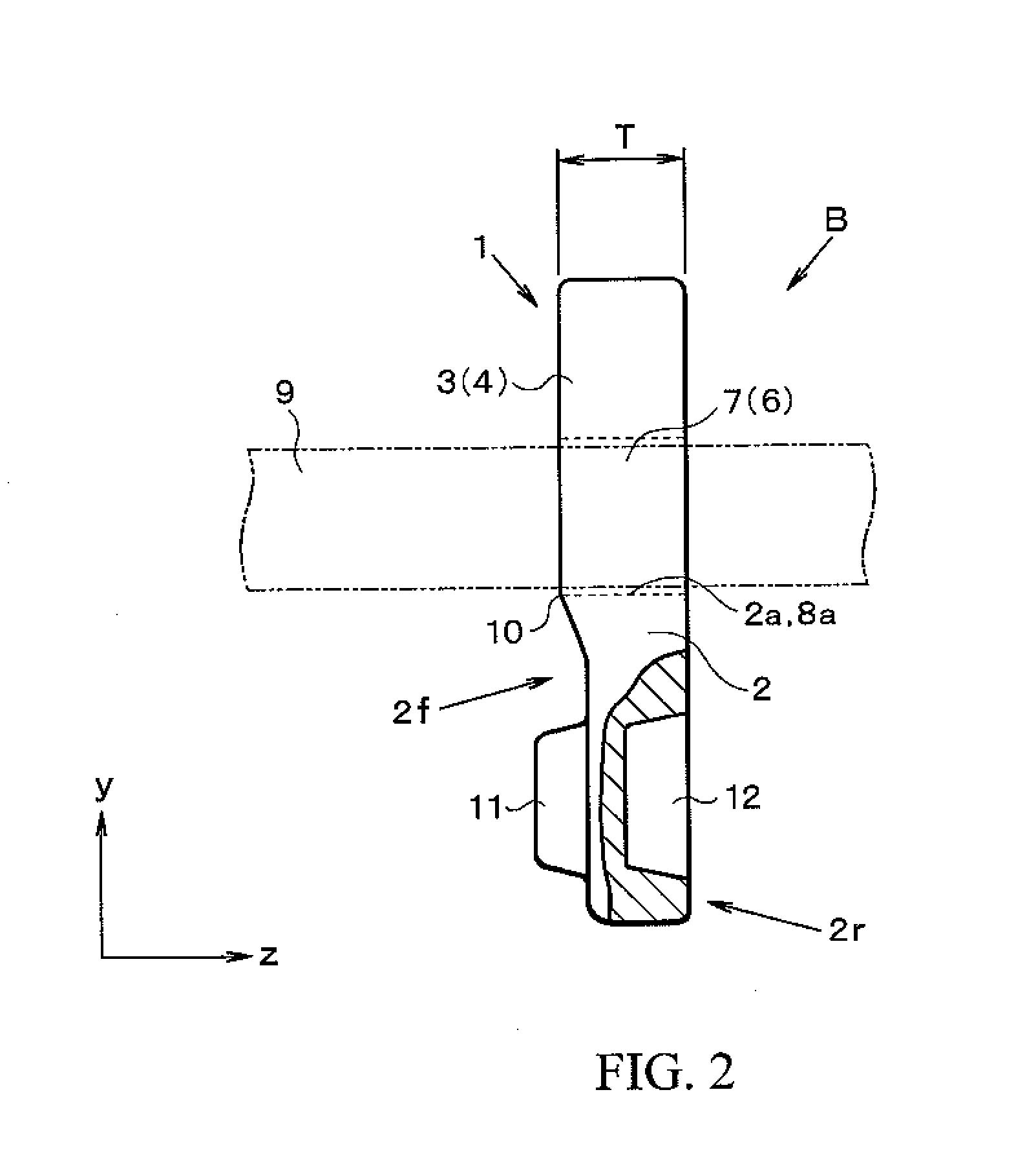
[0030]Next, the present invention will be explained in more detail with reference to the accompanying figures. First of all, a structure of the push type driving belt B of the present invention will be explained with reference to FIGS. 1 and 2. For example, the push type driving belt B is applied to a drive pulley (i.e., an input shaft pulley) and a driven pulley (i.e., an output shaft pulley) of a belt-type continuously variable transmission for the purpose of transmitting a torque between those pulleys. According to the present invention, an element 1 is a plate member made of metal, for example. The element 1 comprises a main body (or a base portion) 2, and both side faces 3 and 4 formed on width ends (i.e., in the direction of x-axis in FIG. 1) of the main body 2 are inclined or tapered. The side faces 3 and 4 thus inclined are contacted frictionally with a (V-shaped) groove 5a of a pulley 5 to transmit the torque.

[0031]Columns 6 and 7 are erected on the width ends of the main b...


PUM


Abstract

To provide a push type driving belt, which is capable of preventing uneven wear of the ring and deterioration in durability of the ring, by preventing a transmission loss resulting from an internal slippage of the ring, and by positioning the ring properly with respect to the element.The push-type driving belt B comprises: an element 1, in which a recess 8 opening toward a diametrically outer circumferential side is formed in a width center thereof; and a ring 9, which is formed of single layer in its thickness direction using elastic material, and which is fitted into the recess 8 of the element 1 to fasten the elements 1 juxtaposed in a circular manner. In the push-type driving belt B, inclined faces 13 and 14 are formed on side faces 9a and 9b of the ring 9 plane symmetrically across a width center plane C; and contact faces 15 and 14 each inclination thereof is identical to that of the inclined faces 13 and 14 and each area thereof is smaller than that of the inclined face 13 and 14 are formed on the inner wall 6a and 7a of width end of the recess 8.

Description

TECHNICAL FIELD[0001]This invention relates to a driving belt, which is formed by annularly juxtaposing a plurality of plate elements in which a recess for holding a ring therein is formed in a width center thereof, and by fastening the elements in a circular manner using a ring. More specifically, the present invention relates to a push type driving belt, which is configured to transmit a torque between two pulleys by pushing the elements sequentially by the following elements.BACKGROUND ART[0002]A push type driving belt is known in the prior art to be used as a power transmission belt in a belt type continuously variable transmission. In general, the push type driving belt is formed by annularly juxtaposing a plurality of plate member called an “element” or a “block” in a same orientation, and by fastening the juxtaposing plate members by an annular member called a hoop or band to be called a “ring” hereinafter). Side faces of the element are inclined to serve as flank faces to be...

Claims


Application Information

Patent Timeline
Patent Type & Authority Applications(United States)
IPC IPC(8): F16G1/24F16G5/16
CPCF16G5/16
Inventor SANO, TOSHINARI
Owner TOYOTA JIDOSHA KK
Why Eureka
Try Eureka