System and method for positioning three-dimensional brackets on teeth

Active Publication Date: 2008-04-24
ALIGN TECH
View PDF4 Cites 39 Cited by
  • Summary
  • Abstract
  • Description
  • Claims
  • Application Information

AI Technical Summary

Problems solved by technology

One shortcoming with this technique is the difficulty in accessing the optimal surface for bracket placement on severely crowded teeth or in teeth where the bonding surface is obstructed by teeth in the opposing arch during jaw closure.
With posterior teeth, the treatment provider may have difficulty seeing the precise position of the

Method used


Image

  • System and method for positioning three-dimensional brackets on teeth
  • System and method for positioning three-dimensional brackets on teeth
  • System and method for positioning three-dimensional brackets on teeth

Examples


Embodiment Construction

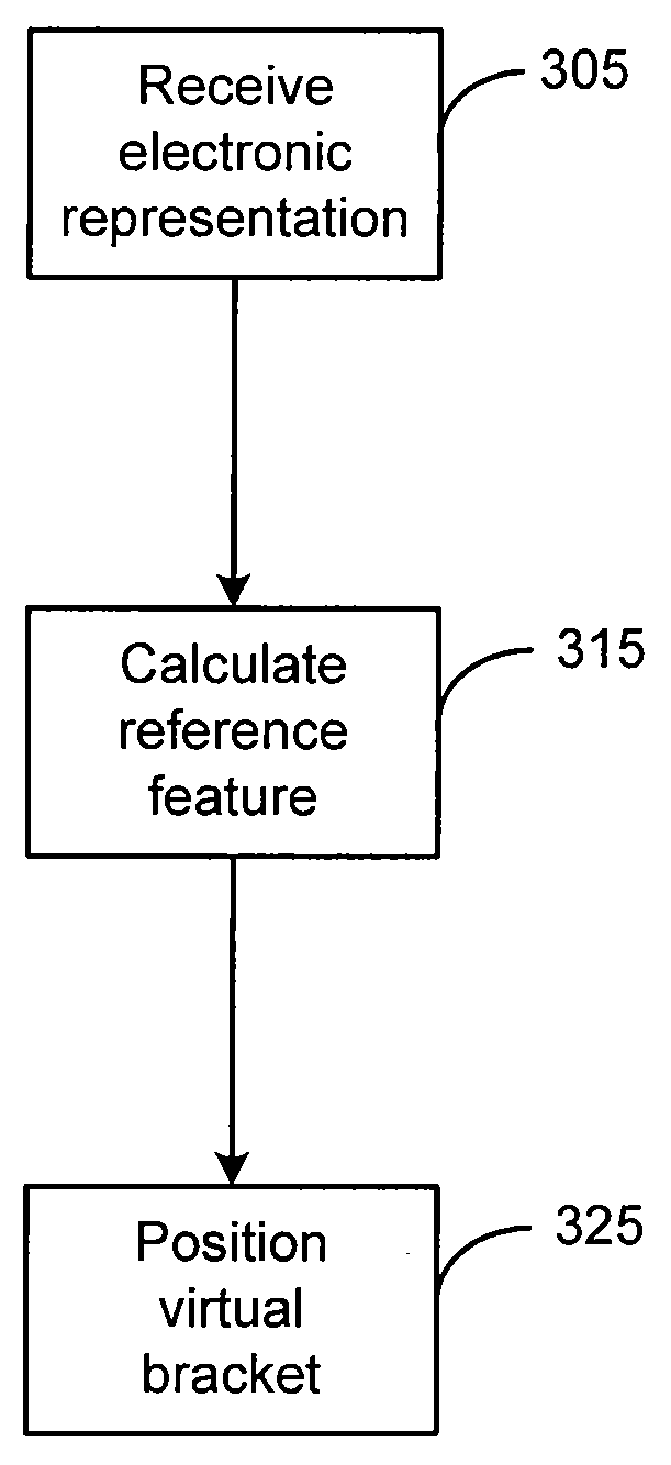
[0021]The present invention may be described herein in terms of various components and processing steps. It should be appreciated that such components and steps may be realized by any number of hardware and software components configured to perform the specified functions. For example, the present invention may employ various electronic control devices, visual display devices, input terminals and the like, which may carry out a variety of functions under the control of one or more control systems, microprocessors or other control devices. In addition, the present invention may be practiced in any number of orthodontic contexts and the exemplary embodiments relating to a system and method for positioning virtual brackets on teeth in a virtual 3D jaw pair model as described herein are merely a few of the exemplary applications for the invention. For example, the principles, features and methods discussed may be applied to any orthodontic treatment application.

[0022]U.S. patent applica...


PUM


Abstract

System and methods for positioning 3D virtual brackets on teeth for the precise positioning of conventional brackets and wire. Various reference features may be calculated for the teeth and used to calculate a position for the virtual bracket. Reference features that are calculated include curve of Spee, Andrew's plane, and a facial axis of the clinical crown for the teeth.

Description

FIELD OF INVENTION[0001]The present invention relates generally to the field of orthodontics, and in particular, to system and method for positioning of three-dimensional brackets on teeth.BACKGROUND OF THE INVENTION[0002]One objective of orthodontics is to move a patient's teeth to positions where the teeth function optimally and are also aesthetically pleasing. Conventional appliances such as braces and wires are applied to the teeth of a patient by an orthodontist. Once mounted on the teeth, the braces exert continual force on the teeth and gradually urge the teeth to their respective ideal position. The orthodontist does this by adjusting the braces over time to move the teeth toward their final destination.[0003]Orthodontic brackets are often bonded directly to the patient's teeth. Typically, a small quantity of adhesive is placed on the base of each bracket and the bracket is then placed on a selected tooth. Before the adhesive is set, the bracket is maneuvered to a desired lo...

Claims


Application Information

Patent Timeline
IPC IPC(8): A61C3/00
CPCA61C7/002A61C2007/004A61C7/146G06T17/20G06T19/20G06T2219/2004G06T2219/2021
Inventor CHEANG, KA MAN
Owner ALIGN TECH
Why Eureka
Try Eureka