Fluid Food Heating Device

a technology of heating device and flue, which is applied in the field of flue food heating device, can solve the problems of complex program flow for operating mechanism, complex mechanism, and complex control system

Inactive Publication Date: 2008-05-08
SANDEN CORP
View PDF6 Cites 2 Cited by
  • Summary
  • Abstract
  • Description
  • Claims
  • Application Information

AI Technical Summary

Problems solved by technology

In the latter method, however, in order to prevent a sensing function from being impaired by the fluid food adhering to the surface of the temperature sensor, it is necessary to use a mechanism and a treatment for cleaning th...

Method used


Image

  • Fluid Food Heating Device
  • Fluid Food Heating Device
  • Fluid Food Heating Device

Examples


Embodiment Construction

An Embodiment of the Present Invention

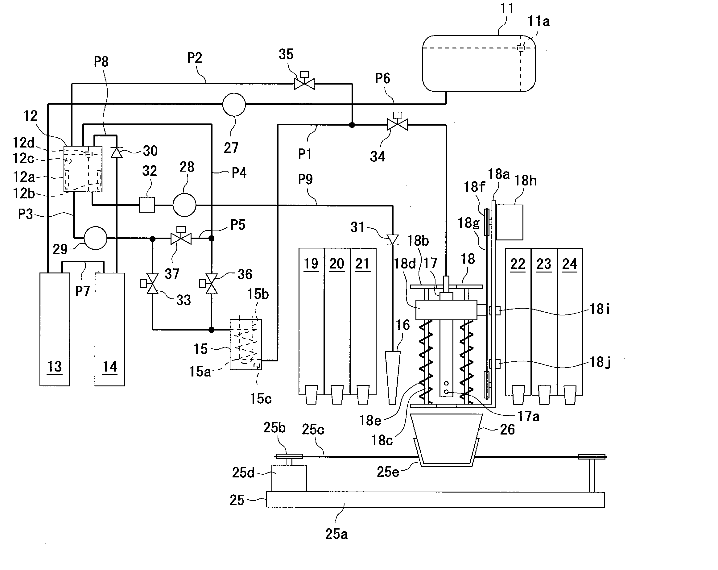
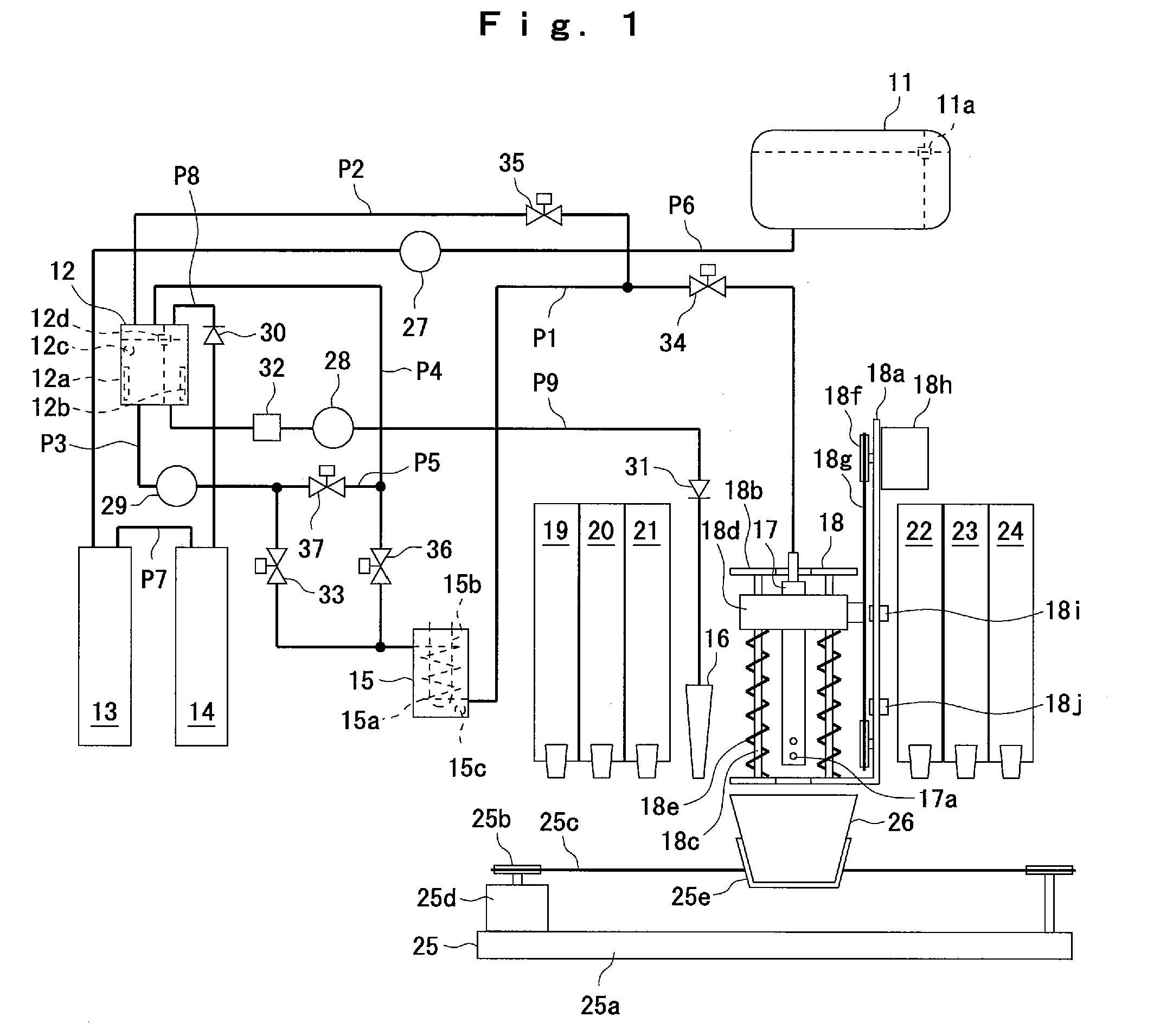
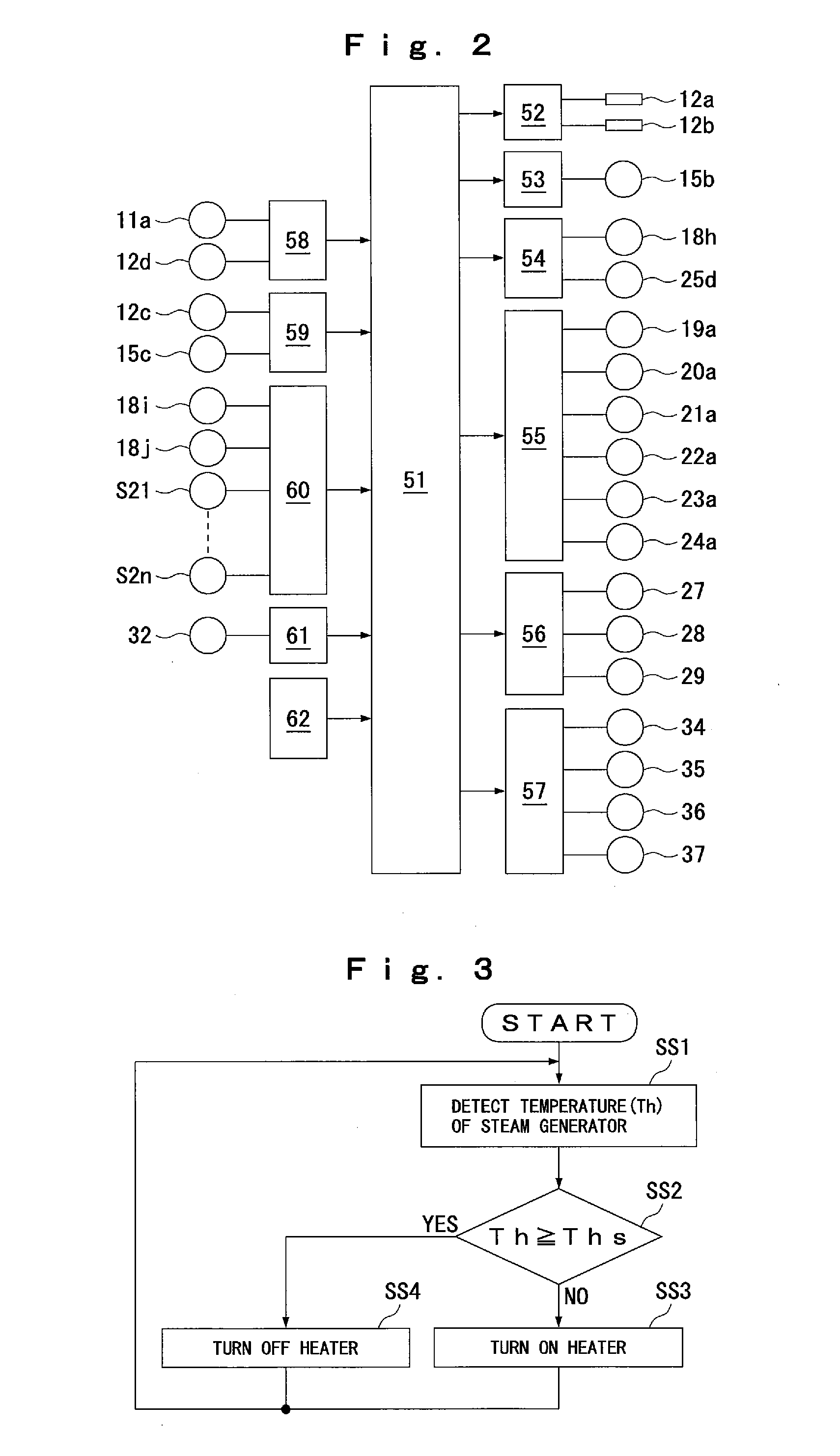
[0023] FIGS. 1 to 9 show an embodiment of the present invention. FIG. 1 is a block diagram of a fluid food heating device, FIG. 2 is an electric circuit diagram of the fluid food heating device shown in FIG. 1, FIG. 3 is a flowchart of a steam generator heating that is executed in the fluid food heating device shown in FIG. 1, FIG. 4 is a flowchart of a cooking of a fluid food that is executed in the fluid food heating device shown in FIG. 1, FIG. 5 is an explanatory diagram of a determination method executed at a steam jetting time determining step in FIG. 4, and FIGS. 6 to 9 are explanatory diagrams of an operation of the fluid food heating device shown in FIG. 1.

[0024] First, with reference to FIG. 1, a mechanism of the fluid food heating device will be described.

[0025] In FIG. 1, the reference numeral 11 denotes a water tank, the reference numeral 12 a cistern, the reference numeral 13 a soft water filter, the reference numeral 14 a steri...


PUM


Abstract

A fluid food heating device detects a temperature of stored water in a cistern through a temperature sensor arranged in the cistern, determines a steam jetting time by using the temperature as a water temperature of a computing equation for determining steam jetting time, and jets steam to a fluid food on the basis of the steam jetting time to heat the fluid food to a target temperature.

Description

BACKGROUND OF THE INVENTION [0001] 1. Field of the Invention [0002] The present invention relates to a fluid food heating device for heating a fluid food to a target temperature by using steam. [0003] 2. Description of the Related Art [0004] A fluid food heating device of this kind includes: a steam generator for generating steam by heating and vaporizing water; and a steam jetting nozzle whose inlet is connected to an outlet of the steam generator via a duct. This fluid food heating device heats the fluid food with the steam jetted from the steam jetting nozzle by providing the steam generated in the steam generator into the steam jetting nozzle inserted into a fluid food. [0005] Because a temperature of the fluid food heated by the jet steam can be controlled by a steam jetting time, there is generally adopted a method including steps of: determining the steam jetting time beforehand according to the quantity and kind of the fluid food to be heated and the like; and stopping a ste...

Claims


Application Information

Patent Timeline
IPC IPC(8): A47J27/06
CPCA47J31/401
Inventor KANUMA, YOSHIHIKOSHIOYA, MORIHISA
Owner SANDEN CORP
Why Eureka
Try Eureka