Variable tuning circuit using variable capacitance diode and television tuner

a capacitance diode and variable technology, applied in the field of variable capacitance diodes and television tuners, can solve the problems of unstable oscillation and low gain, and achieve the effects of increasing noise, extending a variable range, and preventing a reduction of gain

Inactive Publication Date: 2008-06-05
ALPS ALPINE CO LTD
View PDF7 Cites 8 Cited by
  • Summary
  • Abstract
  • Description
  • Claims
  • Application Information

AI Technical Summary

Benefits of technology

[0011]According to the above-mentioned structure, the second inductor is connected in parallel to the variable capacitance element in an AC manner, thereby forming the second parallel resonance circuit. Therefore, it is possible to equivalently vary the value of L such that an L characteristic of the tuning circuit increases in the low frequency band and decreases in the high frequency band, by changing the capacitance of the variable capacitance element. In addition, it is possible to extend a variable range in the high frequency band and ensure the value of L of the inductor to increase the value of Q of a circuit. As a result, it is possible to prevent a reduction in gain, an increase in noise, and unstable oscillation.
[0013]According to the above-mentioned structure, the L characteristic of the tuning circuit becomes the highest in the vicinity of the lowest frequency in the low frequency band, and the inductance of the inductor forming the tuning circuit is larger than that in a circuit according to the related art, when a frequency in the low frequency band is selected. Therefore, it is possible to increase the value of Q of a circuit in the low frequency band by reducing the capacitance of the capacitor connected in series to the variable capacitance element.
[0015]According to the above-mentioned structure, the L characteristic of the tuning circuit is lowered in the vicinity of the highest frequency in the high frequency band, and the inductance of the inductor forming the tuning circuit is smaller than that in a circuit according to the related art, when a frequency in the low frequency band is selected. Therefore, it is possible to extend a variable range in the high frequency band by increasing the value of L of the first inductor that is connected in parallel to the variable capacitance element and by reducing the capacitance of the capacitor that is connected in series to the variable capacitance element.
[0017]According to a variable tuning circuit of a television tuner of an embodiment of the invention, it is possible to extend a variable range in a high frequency band, ensure the value of L of an inductor to increase the value of Q of a circuit in a low frequency band, and prevent a reduction in gain, an increase in noise, and unstable oscillation.

Problems solved by technology

For example, in the tuning circuit 102, impedance is lowered, and thus loss and noise increase, resulting a low gain.
In addition, in the local oscillating circuit 106, the value of Q of the circuit decreases, which results in unstable oscillation.

Method used


Image

  • Variable tuning circuit using variable capacitance diode and television tuner
  • Variable tuning circuit using variable capacitance diode and television tuner
  • Variable tuning circuit using variable capacitance diode and television tuner

Examples


Embodiment Construction

[0023]Hereinafter, exemplary embodiments of the invention will be described in detail with reference to the accompanying drawings.

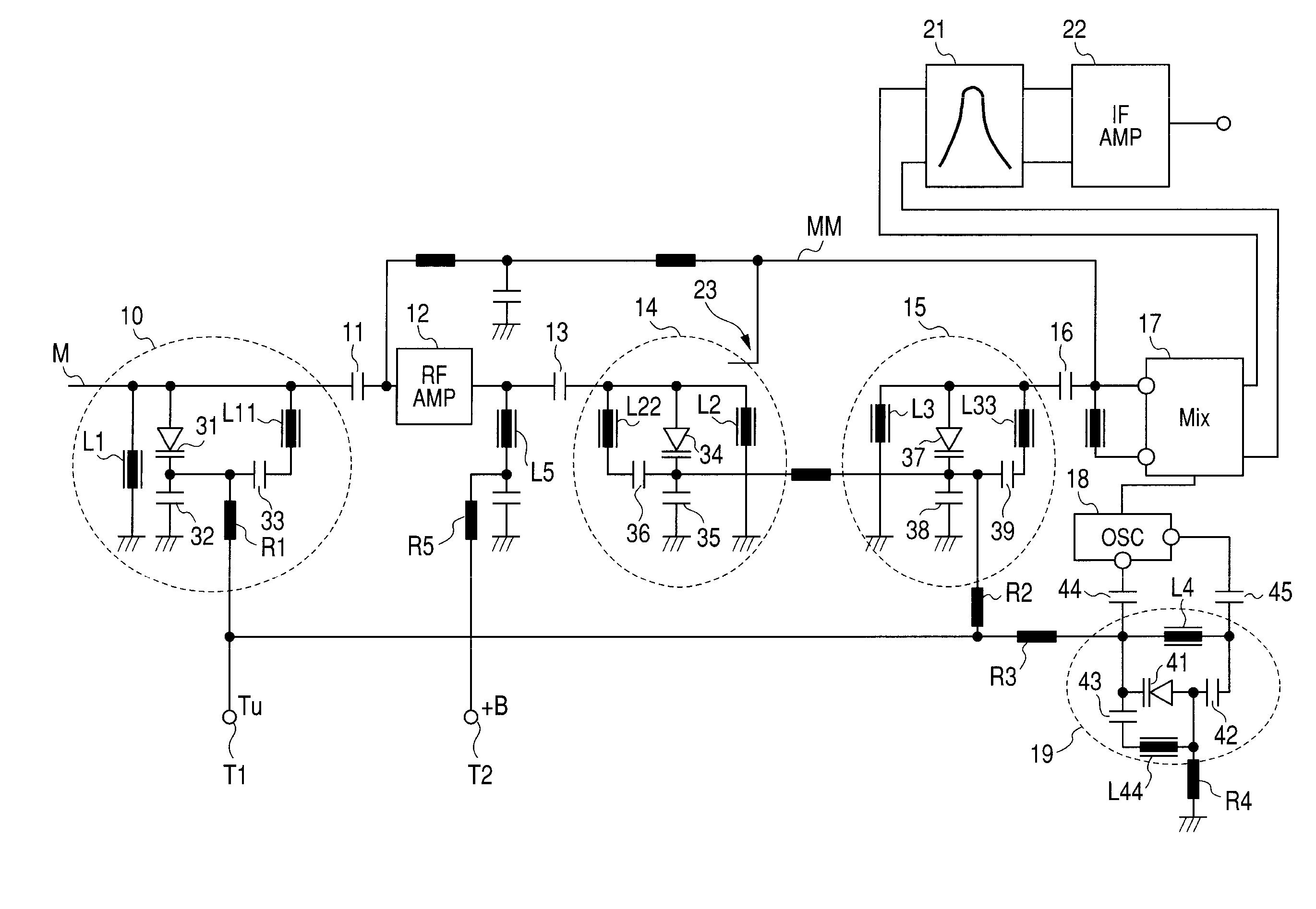
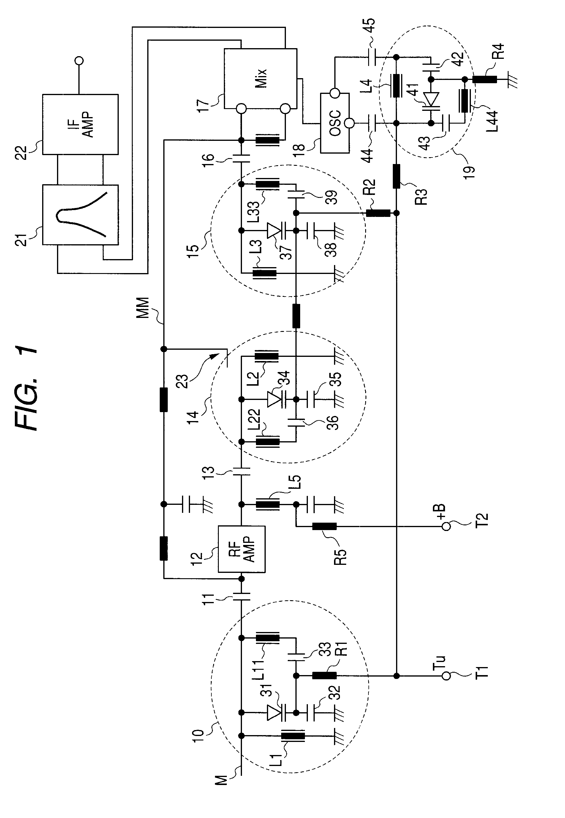
[0024]A television tuner according to an embodiment of the invention is a single band television tuner for receiving UHF, and is provided with four tuning circuits including an input tuning circuit, an RF double tuned circuit, and a local oscillating circuit.

[0025]FIG. 1 is a circuit diagram illustrating the television tuner according to this embodiment, and shows a circuit structure after an input tuning circuit. An input terminal of an input tuning circuit 10 is connected to an output terminal of an antenna (not shown), and an output terminal of the input tuning circuit 10 is connected to an input terminal of a high-frequency amplifying circuit 12 through a coupling capacitor 11. An output terminal of the high-frequency amplifying circuit 12 is connected to a primary tuning circuit 14 of a double tuned circuit through a coupling capacitor 13. An output ...


PUM


Abstract

The invention provides a variable tuning circuit capable of extending a variable range in a high frequency band, ensuring the value of L of an inductor to increase the value of Q of a circuit in a low frequency band, and preventing a reduction in gain, an increase in noise, and unstable oscillation.A variable tuning circuit includes: a first parallel resonance circuit that includes a varactor diode, a capacitor connected in series to the varactor diode, and a first inductor connected in parallel to the varactor diode and the capacitor; and a second parallel resonance circuit that includes a second inductor connected in parallel to the varactor diode with a direct current cut-off capacitor interposed therebetween. When the varactor diode has a maximum capacitance, a resonant frequency of the second parallel resonance circuit is set about a lowest frequency in a variable frequency range.

Description

CLAIM OF PRIORITY[0001]This application claims benefit of the Japanese Patent Application No. 2006-328153 filed on Dec. 5, 2006, which is hereby incorporated by reference.BACKGROUND OF THE INVENTION[0002]1. Field of the Invention[0003]The present invention relates to a variable tuning circuit using a variable capacitance diode and a television tuner provided with the variable tuning circuit.[0004]2. Description of the Related Art[0005]Television tuners are provided with variable tuning circuits using variable capacitance diodes in order to select a received frequency or remove interference waves (for example, see JP-A-10-242805). FIG. 3 is a functional block diagram illustrating the structure of a television tuner disclosed in JP-A-10-242805. In FIG. 3, television radio wave signals received by an antenna 101 are tuned by a tuning circuit 102, and the tuned signals are amplified by a high-frequency amplifying circuit 103. Then, a double tuned circuit 104 selects a received frequency...

Claims


Application Information

Patent Timeline
Patent Type & Authority Applications(United States)
IPC IPC(8): H03J3/06H03J3/20H04B1/18H04B1/26H04N5/44
CPCH03J3/06H03J3/26H03J3/185H03J7/00H04N5/50
Inventor YAMAMOTO, MASAKI
Owner ALPS ALPINE CO LTD
Why Eureka
Try Eureka