
Air Line Adapter Structure Of Suction Apparatus

a suction apparatus and adapter technology, applied in the field of suction apparatus, can solve the problems of limiting the location and place of using such suction apparatus, the air line structure of a conventional suction apparatus still, and the inability of the suction apparatus to be connected to an oxygen delivery device, so as to broaden the scope of application of the suction apparatus

Inactive Publication Date: 2008-06-12
PACIFIC HOSPITAL SUPPLY
View PDF4 Cites 53 Cited by
  • Summary
  • Abstract
  • Description
  • Claims
  • Application Information

AI Technical Summary

Benefits of technology

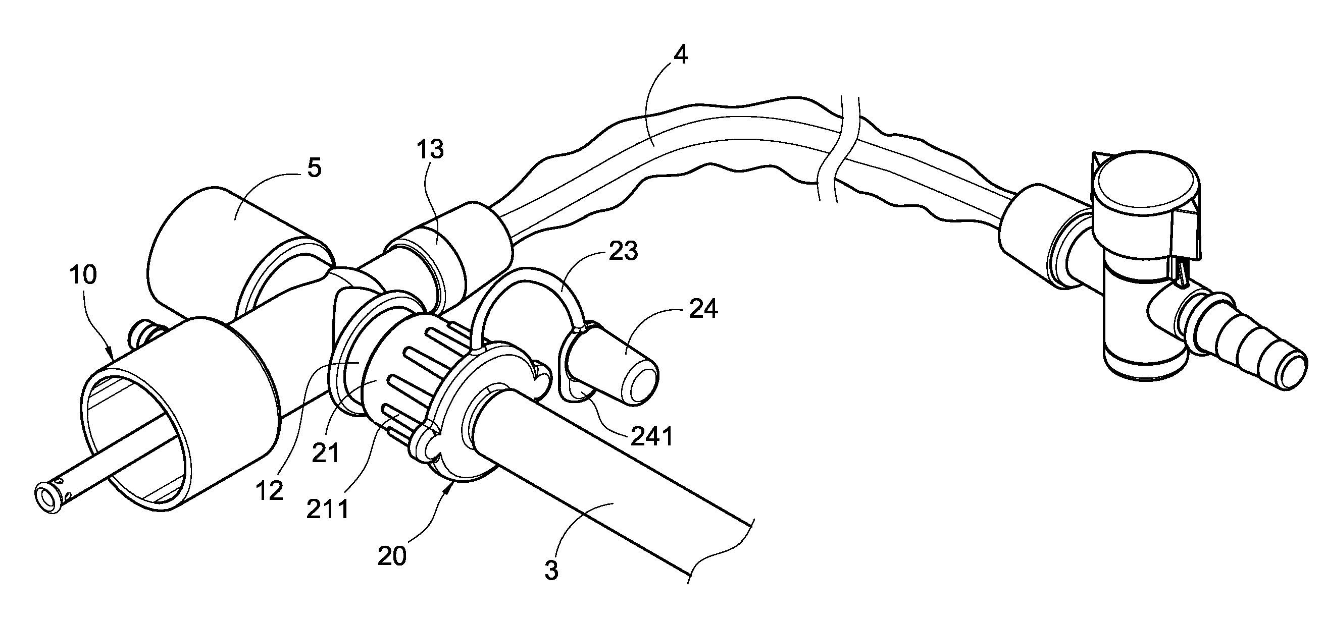
"The present invention is an air line adapter structure for a suction apparatus that allows for timely supplying of oxygen gas to a patient. It includes a connecting tube body with an air tube connector, breathing connector, and suction connector, and an air adapter with a sheathing bushing and connecting tube. The air adapter is connected to the connecting tube body, and the interior of the sheathing bushing is connected to the interior of the connecting tube. The external circumference of the connecting tube is smaller than the external circumference of the sheathing bushing. This allows for a wider range of applications for the suction apparatus."

Problems solved by technology

However, the air line structure of a conventional suction apparatus still has the following issues.
Since a general ward usually does not have a serpentine tube for the breathing apparatus, therefore the suction apparatus cannot be connected to an oxygen delivery device, and the conventional structure greatly limits the location and place of using such suction apparatus.
Further, a breathing tube sleeve has a cylindrical tube, and thus a leak of gas occurs easily at a position that connects the breathing tube sleeve and the cylindrical tube, or the breathing tube sleeve and the cylindrical tube may be detached from each other, when the breathing tube sleeve is connected to the serpentine tube.

Method used


Image

  • Air Line Adapter Structure Of Suction Apparatus
  • Air Line Adapter Structure Of Suction Apparatus
  • Air Line Adapter Structure Of Suction Apparatus

Examples


Embodiment Construction

[0015]The technical characteristics, features and advantages of the present invention will become apparent in the following detailed description of the preferred embodiments with reference to the accompanying drawings. The drawings are provided for reference and illustration only, but not intended for limiting the present invention.

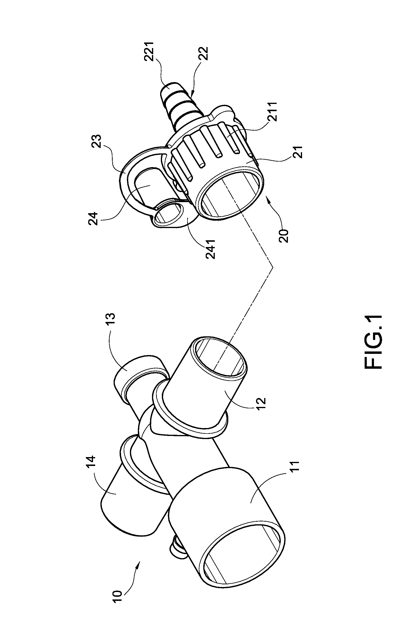
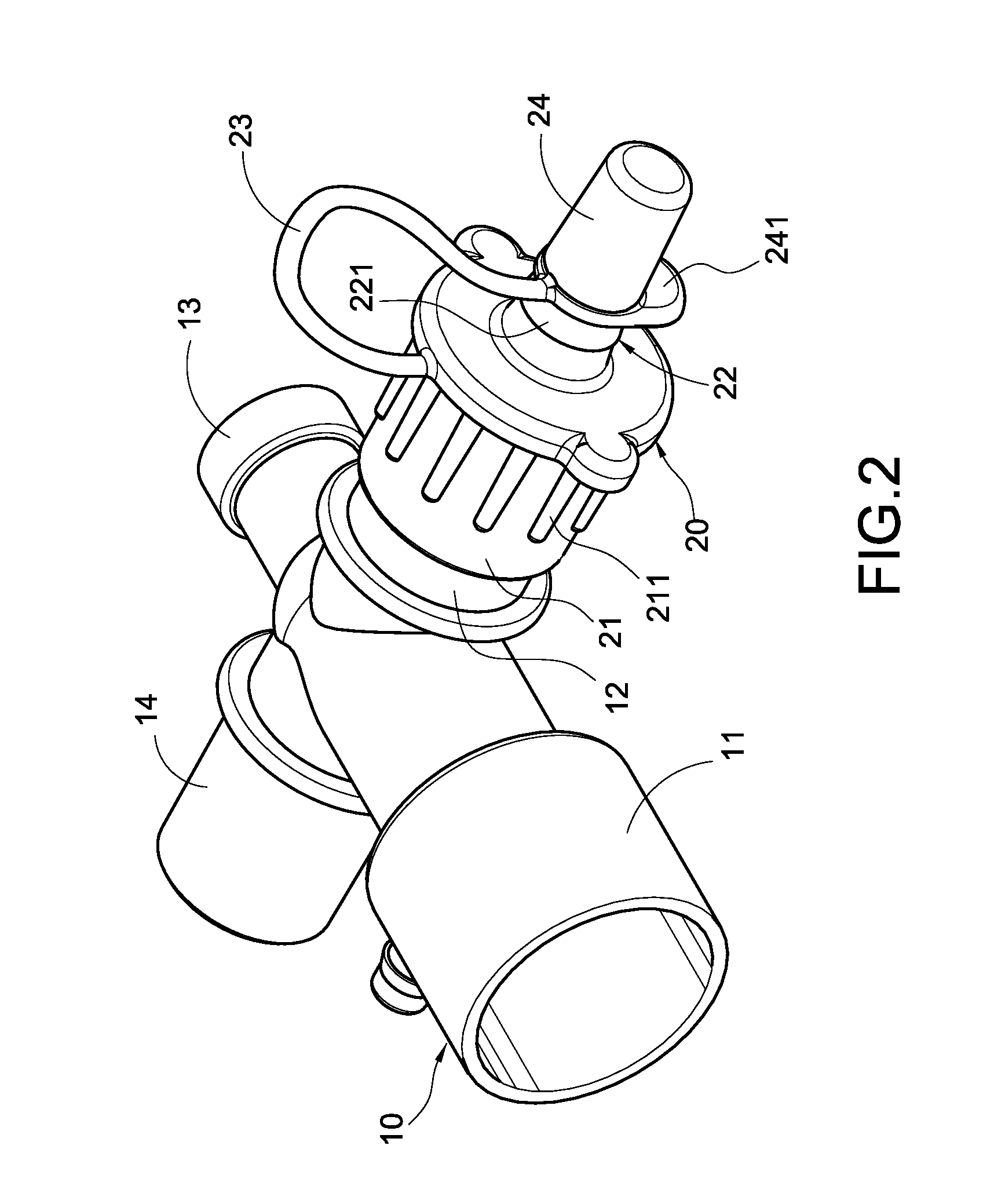
[0016]Referring to FIGS. 1 and 2 for an exploded view and a perspective view of the present invention respectively, the invention provides an air line adapter structure of a suction apparatus, comprising a connecting tube body 10 and an air adapter 20 as described below.

[0017]The connecting tube body 10 can be in a cross-shape (adopted in this embodiment) or any other shape, and the connecting tube body 10 includes an air tube connector 11, a breathing connector 12, a suction connector 13 and a standby connector 14, and the air tube connector 11 is substantially a cylindrical body disposed at the top of the connecting tube body 10; both breathing connecto...


PUM


Abstract

An air line adapter structure includes a connecting tube body and an air adapter. The connecting tube body includes an air tube connector, a breathing connector interconnected with the air tube connector and a suction connector interconnected with the air tube connector and the breathing connector. The air adapter includes a sheathing bushing and a connecting tube extended outward from a sheathed bushing, and the interior of the sheathing bushing is interconnected with the interior of the connecting tube and sheathed onto the breathing connector of the connecting tube body. The external circumference of the connecting tube is smaller than the external circumference of the sheathing bushing, such that the connecting tube can be connected directly to an oxygen tube for timely supplying oxygen to patients and greatly broadening the scope of application of the suction apparatus.

Description

BACKGROUND OF THE INVENTION[0001]1. Field of the Invention[0002]The present invention relates to a suction apparatus, and more particular to a suction apparatus with an air line adapter structure.[0003]2. Description of Prior Art[0004]In general, doctors usually use a suction apparatus having both suction and oxygen supply functions for a tracheotomy patient who needs a breathing apparatus for the treatment, and manufacturers spare no effort to conduct research and development to develop various suction apparatuses including different components and various connections, and thus the application of suction apparatuses become broader and more popular.[0005]A conventional air line structure of a suction apparatus as disclosed in R.O.C. Pat. No. M243213 includes a connecting tube body and a breathing tube sleeve. The connecting tube body includes an air tube connector, a breathing connector and a suction connector, wherein the air tube connector is connected to an air tube, and the brea...

Claims


Application Information

Patent Timeline
Patent Type & Authority Applications(United States)
IPC IPC(8): A62B9/04
CPCA61M16/0463A62B9/04A61M2202/0208A61M16/0816
Inventor LEE, GEORGE
Owner PACIFIC HOSPITAL SUPPLY
Learn More