Integrated approach navigation system, method, and computer program product

a navigation system and integrated approach technology, applied in the field of flight path information systems, can solve the problems of limited availability of satellite-based systems, limited landing procedures at major airports, and inability to provide deviation scales on ian displays, so as to reduce the workload of crew and enhance flight safety

Active Publication Date: 2008-06-12
THE BOEING CO
View PDF16 Cites 68 Cited by
  • Summary
  • Abstract
  • Description
  • Claims
  • Application Information

AI Technical Summary

Benefits of technology

[0010]In light of the foregoing background, the present invention provides systems, computer program products, and methods for displaying navigation performance based flight path deviation information during the final approach segment to a runway and during landing for non-precision flight modes and procedures. Embodiments of the present invention also improve upon the graphical depiction of navigation performance based flight path deviation information. Embodiments of the present invention provide pilots and/or air crew members with a clear, concise display of the dynamic relationship between ANP and RNP, mode and aspect of flight and related procedures, intersecting

Problems solved by technology

However, due to the effect of wind on the airplane's flight path and other factors, the actual heading flown by the aircraft often differs from the predefined flight plan, thus requiring constant adjustment to the airplane heading to maintain the desired course.
While these sources can provide adequate positioning information, they each have individual drawbacks.
For example, while systems such as GPS systems, which acquire positioning information from satellites, can provide positioning information to an aircraft virtually anywhere, the availability of such satellite-based systems can be limited due to factors such as satellite geometry.
And while ILS-type systems provide very accurate positioning information, these types of systems are

Method used


Image

  • Integrated approach navigation system, method, and computer program product
  • Integrated approach navigation system, method, and computer program product
  • Integrated approach navigation system, method, and computer program product

Examples


Embodiment Construction

[0023]The present invention now will be described more fully hereinafter with reference to the accompanying drawings, in which some, but not all embodiments of the invention are shown. This invention may, however, be embodied in many different forms and should not be construed as limited to the embodiments set forth herein; rather, these embodiments are provided so that this disclosure will be thorough and complete, and will fully convey the scope of the invention to those skilled in the art. Like numbers refer to like elements throughout.

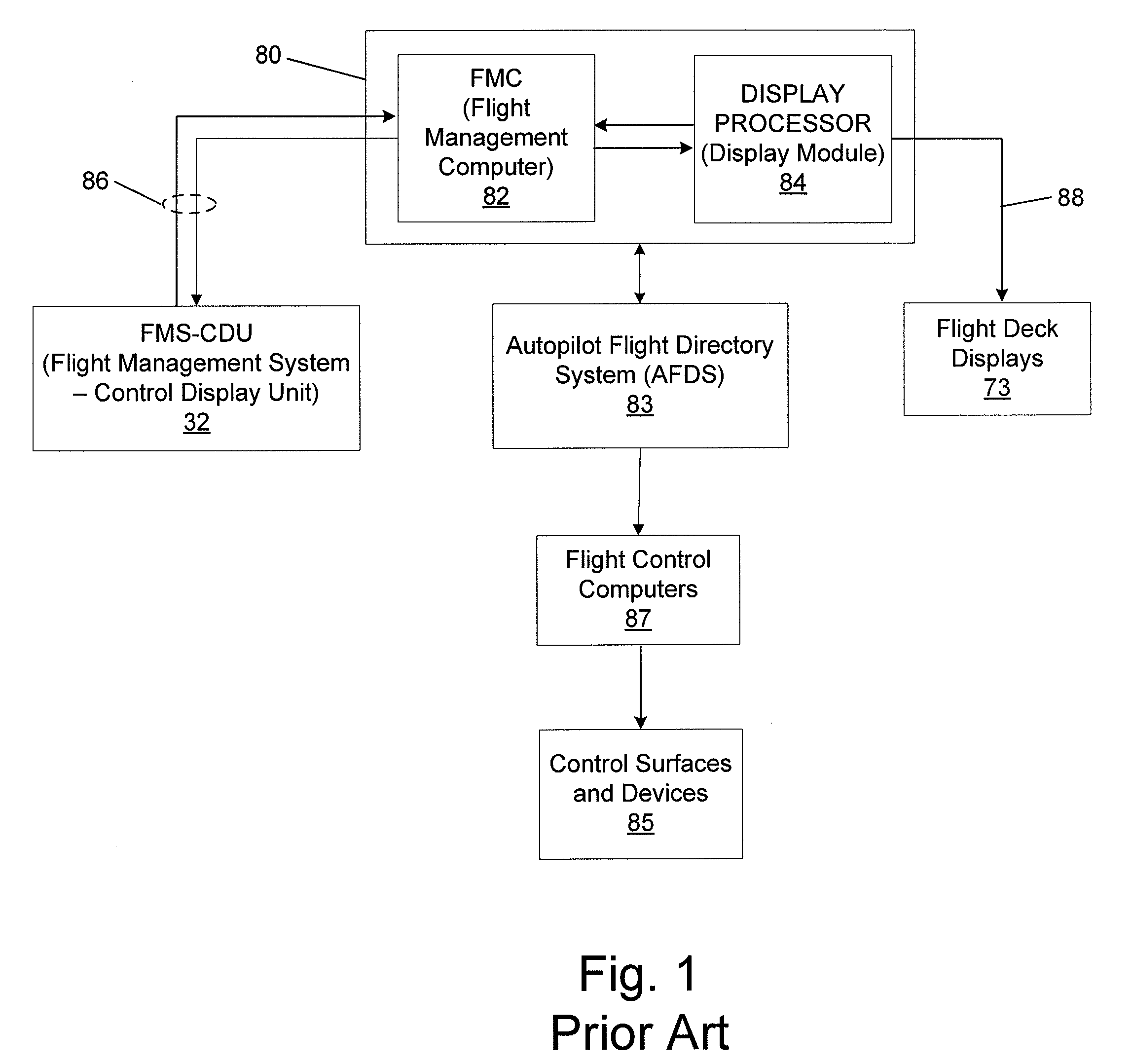
[0024]FIG. 1 illustrates a block diagram of the primary components of a typical modern commercial flight management system. Although the present invention can be used with the modern commercial flight management system, as discussed below, it should be understood, however, that the present invention could be implemented by any number of different electronic systems, including control displays for various other types of vehicles, without departing f...


PUM


Abstract

Systems, computer program products, and methods for displaying navigation performance based flight path deviation information during the final approach segment to a runway and during landing of non-precision flight modes are provided. Improved graphical depictions of navigation performance based flight path deviation information provide pilots and flight crew members with clear, concise displays of the dynamic relationship between ANP and RNP, mode and aspect of flight and related procedures, intersecting flight paths, and current actual flight path deviation from a predefined flight path during the final approach segment to a runway and during landing. For example, an enhanced IAN display may include NPS-type deviation scales to show RNP/ANP relationships and predetermined RNP markers to alert the pilots and flight crew members that the FMC has transitioned from an NPS display for RNAV (LNAV/VNAV) flight procedures to an enhanced IAN display for a non-precision (non-xLS) approach and/or landing.

Description

FIELD OF THE INVENTION[0001]The present invention relates generally to flight path information systems, and, more particularly, to flight path information assemblies, methods, and computer program products for displaying flight path deviation information based on navigation system performance.BACKGROUND OF THE INVENTION[0002]In modern commercial aircraft, if not already available electronically, a flight crew makes flight plan entries and modifications through a Flight Management System—Control Display Unit (FMS-CDU). The FMS-CDU is an electronic module containing a keyboard on its lower face half and an electronic display on its upper face half. By keying entries into the keyboard, the flight crew can build or modify a route into the Flight Management Computer (FMC) by typing in a series of waypoints which are then displayed, in text form, on the upper half of the FMS-CDU display.[0003]An additionally provided display is a navigation (map) display. In contrast to the text display o...

Claims


Application Information

Patent Timeline
IPC IPC(8): G01C21/00G05D1/00
CPCG01C21/00G01C23/005G01C23/00G08G5/025G08G5/0021
Inventor DAVIS, ROBERT B.BOORMAN, DANIEL J.GAGNON, L. KIRKGOODMAN, WILLIAM L.JACOBSEN, ALAN R.MILLER, WILLIAM A.MITCHELL, JAMES E.RILEY, VICTOR A.ROYCE, WILLIAM F.TAFS, WILLIAM D.
Owner THE BOEING CO
Why Eureka
Try Eureka