Interactive data view and command system

a command system and data view technology, applied in the field of interactive data view and command system, can solve the problems of physical impairment, delay in decision making, and separation of the electronic camera from the human eye, and achieve the effects of improving system characteristics, good basis for determining the orientation of the eyeball, and time-consuming and demanding performan

Active Publication Date: 2008-07-03
APPLE INC
View PDF31 Cites 172 Cited by
  • Summary
  • Abstract
  • Description
  • Claims
  • Application Information

AI Technical Summary

Benefits of technology

[0037]In accordance with one aspect of the optical input unit, the optical apparatus is wearable by an operator and capable of scanning the retina up to frequencies of 100 Hz and an image falling onto the eye, in particular a retinal reflex image. The optical input unit is a part of an interactive data view and command system, with the particular advantage that, for operating the system, a least possible effort on the part of the operator is necessary. The information to be queried can be transmitted to the operator with shortest possible delay either in the form of image signals and / or in the form of signals for controlling further information reproduction devices that can be operated e.g. on an acoustic or other sensory basis. A system thus results that is distinguished by a highest measure of directness of the interactive information exchange.
[0081]The capturing of the retinal reflex in which the retinal reflex of natural or artificial light is intermittently or partial captured as the signal reflected back from the eye has turned out to be useful. A full capturing of the retinal reflex is both time consuming and demanding on performance. On the other hand, a capturing of the retinal reflex is useful inasmuch as it allows the relationship of the perceived field of view to the retina to be directly determined. Indeed, as noted above, a processing of the captured retinal reflex allows both retinal features such as e.g. the fovea centralis or the blind spot as well as the reflex image of the light falling onto the eye to be determined. The network of blood vessels present in the choroid coat also becomes visible through appropriate processing of the retinal reflex image, which yields a very good basis for determining the orientation of the eyeball. If the retinal reflex is thus captured intermittently or partially, the processing complexity can be reduced without sacrificing an exact determination of the relationship of the perceived field of view to the retina. Naturally, the retinal features can be followed without capturing the retinal reflex. For example, the blood vessels of the choroid coat can be recognized via their radiation of heat that is visible in the infrared range.

Problems solved by technology

In many of these applications, it is disadvantageous that the electronic camera is a “second eye system” separate from the human eye.
This disadvantage is due to the fact that the images are seen from another recording location and that additionally, the pictures on the image screen are presented at another observation location than the eye.
Thus, the human eye must constantly change between the direct observation and the indirect observation while taking into account different observation angles, different image details, and different size ratios which leads to physical impairments and delays when decisions must be made.

Method used


Image

  • Interactive data view and command system
  • Interactive data view and command system
  • Interactive data view and command system

Examples


Embodiment Construction

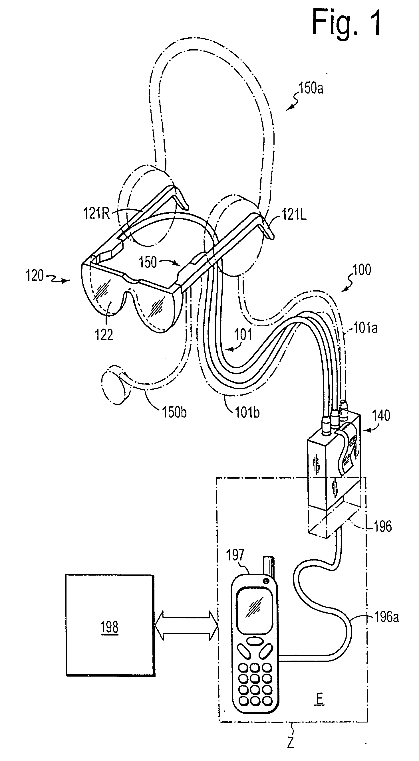
[0114]FIG. 1 illustrates schematically an interactive data view and command system 100 in a broadest sense of the word, as an information system. The information system 100 is embodied in the form of an interactive spectacle system 120, i.e. interactive spectacles 120, which comprise two optical apparatuses 150. Preferably, the optical apparatuses 150 are respectively located in an inner side of a left 121L or right 121R temple of the spectacles 120. Depending on the field of application, other arrangements of the optical apparatuses that do not disturb the view, e.g. in the region of a bridge 122 of the spectacles 120 that crosses the root of the nose of a user are also appropriate.

[0115]The optical apparatus is connected to a processor unit 140 via connection lines 101. If the optical apparatuses comprise photodetectors and / or light sources, the connection lines serve the transmission of electrical detection and / or control signals. The photodetectors and / or light sources can, howe...


PUM


Abstract

A method and information system for capturing signals, for processing signals, and for providing signals at least partially based on, or bearing correlation to, the captured signals is disclosed. The information system includes a signal input unit, a wireless communication unit, and an output unit. The signal input unit (preferably an optical signal unit) is constructed and is positionable to capture signals associated with an eye. The output unit is constructed to provide information based on the captured signals or to provide information as a function of the captured signals or in correlation with the captured signals.

Description

FIELD OF THE INVENTION[0001]The present invention relates to an interactive data view and command system including a wearable signal input unit providing high level of wearer comfort, performance and flexibility.BACKGROUND OF THE INVENTION[0002]Recording, processing and reproduction of images grows with an increasing demand for information and their clear graphic visualization. Electronic image processing also involves processing of images taken by cameras, scanning systems and sensors in the visible light spectrum as well as in other sections of the electromagnetic spectrum such as the infrared, the radio frequency and the X-ray frequency range. After electronic processing, many images are reproduced either as individual images or as moving images on an image reproduction screen such as a display for presenting the information to the eye.[0003]There are special image contents easier recognizable by electronic image processing using, for example, local frequency filtering, margin sh...

Claims


Application Information

Patent Timeline
Patent Type & Authority Applications(United States)
IPC IPC(8): B60Q1/00G06K9/00G02C7/14G02B17/00G02B27/00G02B27/01G06F3/01
CPCG02B27/017G02B27/0172G05D1/0038G02B2027/0178G02B2027/0132G05D1/0016
Inventor EBERL, HEINRICH A.EBERL, ROLAND H.C.DICKERSON, DAVID P.KONIGSTEIN, KARSTENJOCHHEIM, EDGAR
Owner APPLE INC
Why Eureka
Try Eureka