
Piece of furniture such as a bed or a chair

a furniture and chair technology, applied in the field of furniture pieces, can solve the problems of rigid fixing of arms, and achieve the effect of good welding and simple and inexpensive manufacturing methods

Inactive Publication Date: 2013-08-06
LINAK AS
View PDF19 Cites 4 Cited by
  • Summary
  • Abstract
  • Description
  • Claims
  • Application Information

AI Technical Summary

Benefits of technology

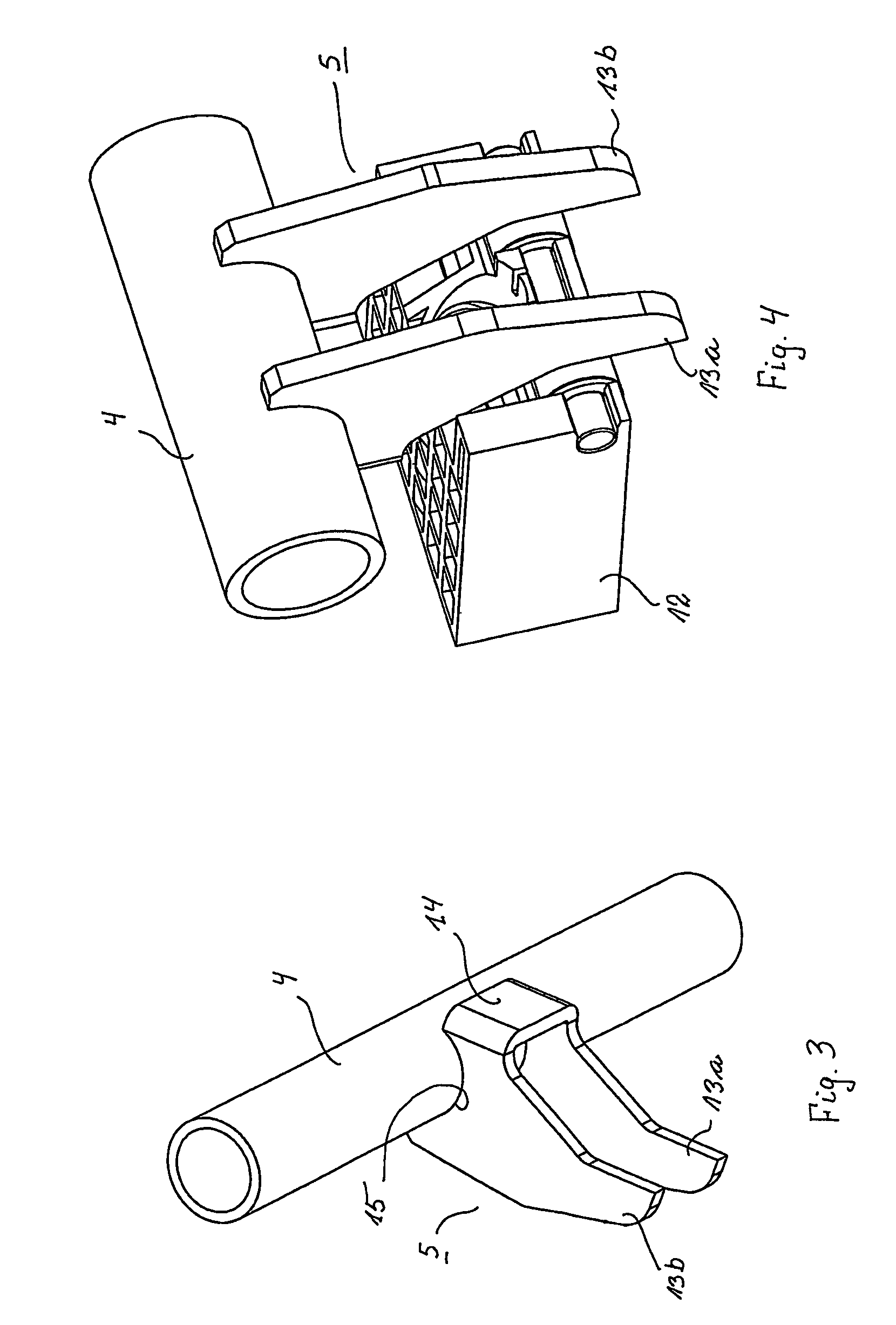
The invention provides a claw-shaped arm for a pivot shaft that is simple and inexpensive to manufacture. The arm is made from a single component cut and bent from a plate material, and the correct distance between its two legs is ensured. The arm has a notch for easy placement on the pivot shaft, which is semicircular in shape and provides a stable fixing to the shaft. The arm also has a rectilinear plate that can be used for additional fixing, and the legs of the arm are hardened to minimize wear from engagement with the sliding element.

Problems solved by technology

A further issue is also a robust and rigid fixing of the arms to the pivot shafts as the arms are heavy loaded.

Method used


Image

  • Piece of furniture such as a bed or a chair
  • Piece of furniture such as a bed or a chair
  • Piece of furniture such as a bed or a chair

Examples


Embodiment Construction

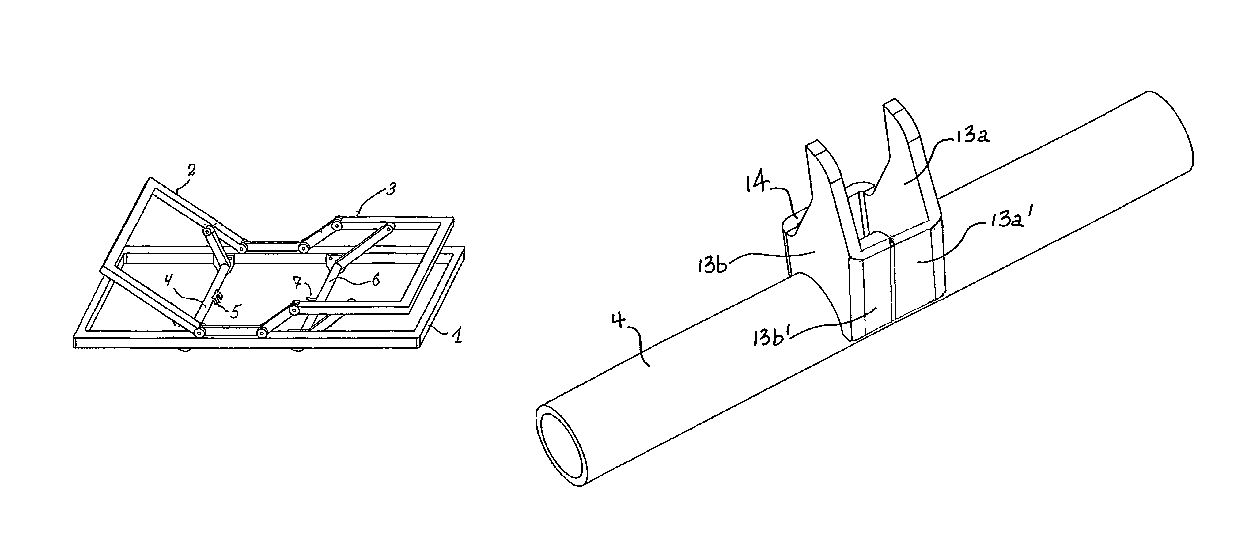
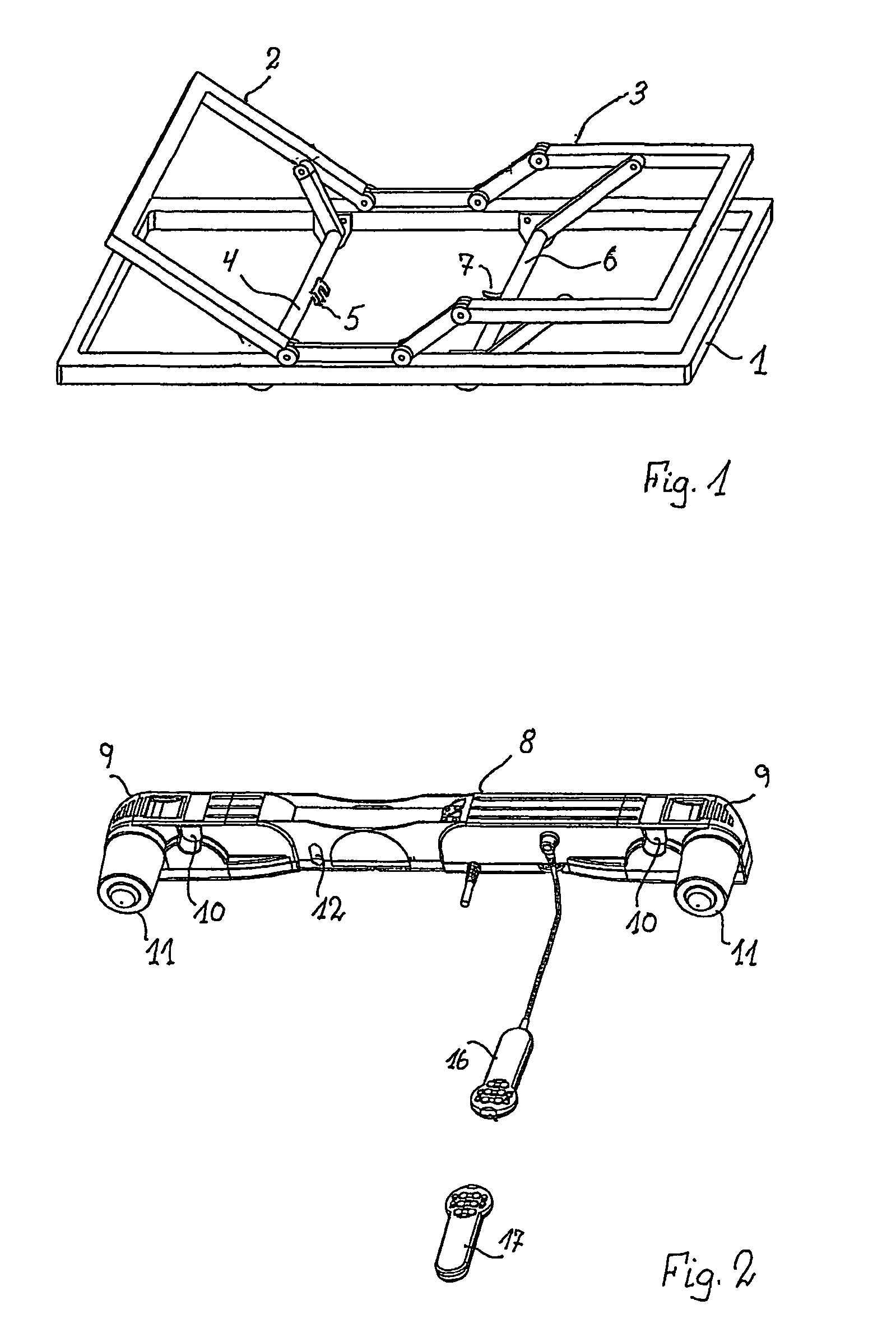
[0016]As it appears from FIG. 1, the slatted bed comprises a frame 1 in which a backrest section 2 and an articulated legrest section 3 is embedded. For the backrest section 2 a transverse pivot shaft 4 with a short arm 5 fixedly mounted onto it is embedded in the frame. Correspondingly, there is a shaft 6 with a short arm 7 for the legrest section.

[0017]The movement of the backrest and legrest section 2,3 is obtained with a drive unit in the nature of a dual linear actuator as shown in FIG. 2. The drive unit comprises a housing 8 with a sliding cover 9 at each end, the covers giving access to an opening 10 for the respective pivot shafts 4,6. In connection with the shaft openings 10 there is a linear drive driven by a motor 11 mounted perpendicular to the housing. Over a worm gear, the motor drives a spindle with a spindle nut designed as a sliding element 12. The sliding element is fixed against rotation in the housing 8 and by rotation of the spindle the sliding element 12 is mov...


PUM


Abstract

An item of furniture includes a frame mounting two adjustable sections which each includes a pivot shaft to cause pivoting of the respective section relative to the frame. Each pivot shaft mounts a claw-shaped arm having two legs. A dual linear actuator having openings at its opposite ends is suspended from the two claw-shaped arms and is operable to rotate the pivot shafts by engagement of sliding spindle nuts therein with the respective claw-shaped arms.

Description

BACKGROUND OF THE INVENTION[0001]1. Field of the Invention[0002]The present invention relates to a piece (or item) of furniture such as a bed or a chair.[0003]2. The Prior Art[0004]For explanation of the invention reference is made to WO 03 / 04 5195 A1 Cimosys Limited which deals with a bed with an adjustable backrest and legrest section embedded in a frame. For elevating the backrest section in a pivoting manner, there is a transverse pivot shaft embedded in the frame, the pivot shaft having at each end a lever which with an end engages the backrest section. In a similar manner there is a pivot shaft and lever for moving the legrest section. A drive unit with a linear drive at each end is mounted on the two pivot shafts. The linear drives have a spindle with a nut designed as a sliding element, the sliding elements being engaged with a short arm secured to the respective pivot shafts. The arm is claw-shaped and sits astride the spindle facing an end of the sliding element. Tradition...

Claims


Application Information

Patent Timeline
IPC IPC(8): A47C1/02
CPCA47C20/041Y10T74/1892
Inventor NIELSEN, JENS JORGENLORENZEN, KURT
Owner LINAK AS
Learn More