Heat exchanger device and a method for manufacturing the same

a technology of heat exchanger and heat exchanger plate, which is applied in the direction of heat exchange apparatus, heat exchanger fastening, stationary tubular conduit assembly, etc., can solve the problems of affecting pressure loss and flow rate, and achieve the effect of reducing the risk of buckling the pla

Inactive Publication Date: 2007-06-12
BOSAL EMISSION CONTROL SYST
View PDF15 Cites 5 Cited by
  • Summary
  • Abstract
  • Description
  • Claims
  • Application Information

AI Technical Summary

Benefits of technology

[0028]In order to be able to manufacture a recuperator in the above-mentioned way, it is necessary to use a welding technique that has a selective and localized propagation of heat, which diminishes the risk of buckling the plates when performing the welding. One welding technique suitable for the manufacturing of a recuperator in accordance with the invention is laser welding.

Problems solved by technology

When the heat-absorbing medium is flowing in the cell, the medium expands in the cell, which affects the pressure losses and the flow rate.

Method used


Image

  • Heat exchanger device and a method for manufacturing the same
  • Heat exchanger device and a method for manufacturing the same
  • Heat exchanger device and a method for manufacturing the same

Examples


Embodiment Construction

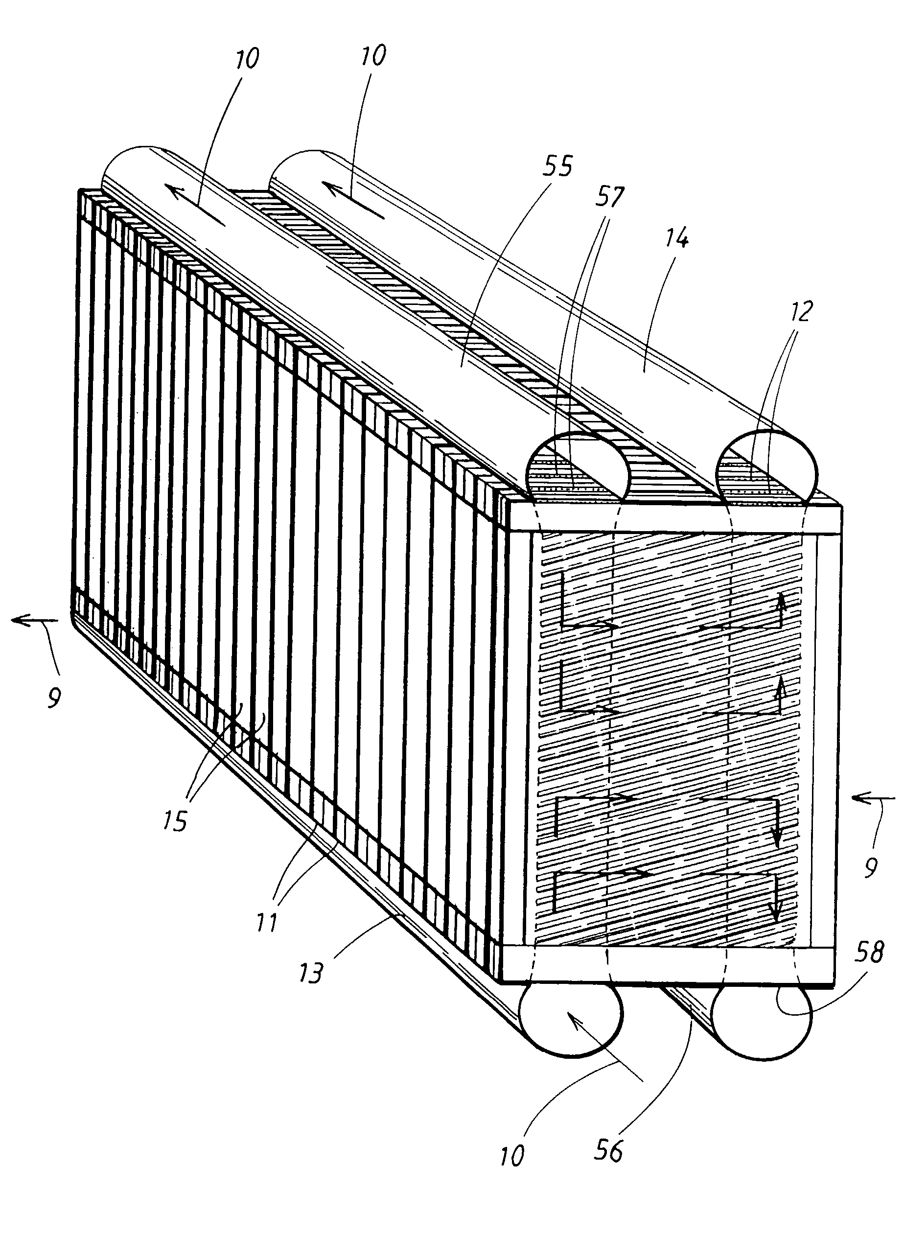
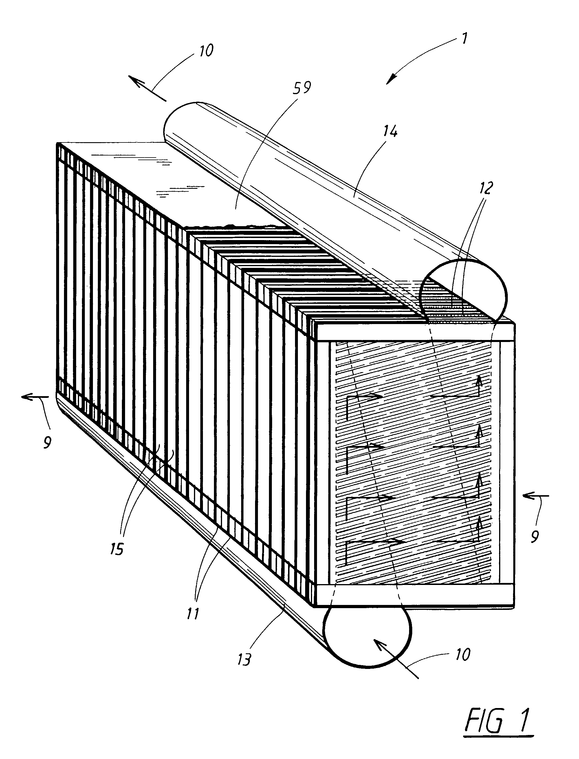
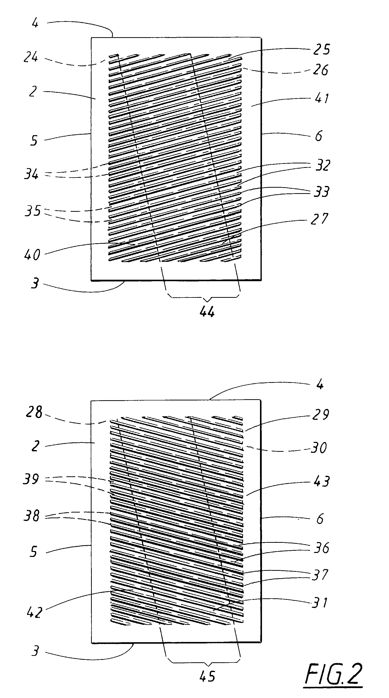
[0041]In FIGS. 1–9, descriptive exemplary representations of the invention are shown as a plate heat exchanger 1 of a type that is preferably intended for use with a gas turbine and in which the plate heat exchanger includes a number of corrugated plates 2. The features that recur in the different Figs. are denoted with the same reference numbers. Each of the plates 2 has a first edge part 3 and an opposing second edge part 4, a third edge part 5 and an opposing fourth edge part 6. Between the corrugated plates 2, first and second flow channels 7, 8 are arranged, where every first flow channel is arranged to have a through flow of a heat-emitting medium 9. This is depicted in FIG. 7 and is designated by the symbol of an out-going arrow exemplifying combustion gases from a gas turbine, and every second is arranged to have a through flow of a heat absorbing medium 10 that is depicted in FIG. 7 and is designated by the symbol of an incoming arrow representing incoming air. The first fl...


PUM


Abstract

Method and device for providing a plate heat exchanger (1) having a number of corrugated plates (2). Between the corrugated plates (2) first and second flow channels (7, 8) are arranged, which first flow channels (7), via first inlet openings (11) and first outlet openings (12), are connected essentially parallel to in-going and out-going junction channels (13, 14). The plates (2) are fitted to each other in pairs, forming cells (15) including an inner spacing element (16) welded to and between the plates, and outer spacing elements (17) welded to the plates (2) on the sides of the plates (2) facing away from each other, along at least two of the edge parts (3–6). The cells (15) are stacked against each other and joined together by welding of the outer spacing elements (17), and in that said in-going and out-going junction channels (13, 14) are welded to said first inlet openings (11) and first outlet openings (12) respectively.

Description

CROSS REFERENCE TO RELATED APPLICATIONS[0001]The present application is a continuation patent application of International Application No. PCT / SE02 / 00559 filed 22 Mar. 2002 which was published in English pursuant to Article 21(2) of the Patent Cooperation Treaty, and which claims priority to Swedish Application No. 0101085-9 filed 27 Mar. 2001. Both applications are expressly incorporated herein by reference in their entireties.BACKGROUND OF INVENTION[0002]1. Field of the Invention[0003]The present invention refers to a heat exchanger device, also called recuperator, which advantageously is intended for use with a gas turbine for stationary use in a small-scale power station or for mobile use in a vehicle. The invention also refers to a method for manufacturing the heat exchanger.[0004]2. Background Art[0005]A heat exchanger of the above-mentioned type is used, for example, in small-scale power stations, for mobile use or in a reserve power station. In at least these applications, i...

Claims


Application Information

Patent Timeline
Patent Type & Authority Patents(United States)
IPC IPC(8): F28F3/10F28D9/00F28F3/04
CPCF28D9/0031F28F3/046Y10S165/387F28F2275/067
Inventor LAGERSTROM, GUNNARXIE, MAX
Owner BOSAL EMISSION CONTROL SYST
Why Eureka
Try Eureka