Battery having electrolyte injecting plug

a technology of electrolyte and battery, which is applied in the field of batteries, can solve the problems of deterioration, leakage of electrolyte, and more difficulty in spot-welding a large-sized electrolyte,

Inactive Publication Date: 2002-09-10
GS YUASA INT LTD
View PDF9 Cites 47 Cited by
  • Summary
  • Abstract
  • Description
  • Claims
  • Application Information

AI Technical Summary

Benefits of technology

In accordance with the first aspect of the present invention, an electrolyte injecting plug is laser-welded to an electrolyte injecting port at the periphery thereof with its entire part or forward end being inserted therein. In this arrangement, the electrolyte injecting plug can be fixed to the electrolyte injecting port to assure that the electrolyte injecting port is plugged. Further, since the electrolyte injecting plug can be easily welded to the electrolyte injecting port at the periphery thereof by allowing a laser spot to run, the electrolyte injecting port cannot be insufficiently plugged even if the size of the electrolyte injecting port is increased to increase the periphery of the electrolyte injecting plug to be welded. Moreover, since metals are welded to each other to plug the electrolyte injecting port free from packing or O-ring, the airtightness of the sealed portion cannot be deteriorated.
In accordance with the second aspect of the present invention, the electrolyte injecting plug can be securely fitted in the electrolyte injecting port and thus cannot fall into the interior of the battery case.
Further, by arranging the electrolyte injecting plug such that the outer surface thereof is almost flush with the surface of the outer edge of the electrolyte injecting port, the outer surface of the electrolyte injecting plug can be prevented from protruding from the battery case. In this arrangement, the electrolyte injecting plug does not give an offense to the eye or an obstruction in handling.
Further, the electrolyte injecting plug can form a male thread on the forward end thereof while the electrolyte injecting port can form a female thread on the inner surface thereof to engage with the male thread so that the electrolyte injecting plug fitted in the electrolyte injecting port can be securely fixed thereto.
In accordance with the fourth aspect of the present invention, since the provision of a curved portion on the outer edge of the electrolyte injecting port and the electrolyte injecting plug, it is possible to prevent the diffusion of heat during laser welding and hence secure the welding of metal to metal.

Problems solved by technology

Consequently, it is made more difficult to spot-weld a large-sized electrolyte injecting plug 8 completely to the electrolyte injecting port 2 leaving no gap therebetween.
However, because the packing 9 or O-ring is made of a rubber or synthetic resin material, it has the following problems.
Namely, it is liable to deterioration due to aging and hence denaturation due to contact with the electrolyte or heat generated upon excessive charge and discharge.
Accordingly, it may cause the deterioration of the airtightness of the sealed portion resulting in the leakage of the electrolyte.
Further, if the electrolyte injecting plug 8 having a male thread formed at the forward end thereof or a flange portion 8b thereon is used, a large protrusion is formed at the sealed portion to an extent such that it gives an offense to the eye or an obstruction in handling.
Further, since the electrolyte injecting plug can be easily welded to the electrolyte injecting port at the periphery thereof by allowing a laser spot to run, the electrolyte injecting port cannot be insufficiently plugged even if the size of the electrolyte injecting port is increased to increase the periphery of the electrolyte injecting plug to be welded.
Moreover, since metals are welded to each other to plug the electrolyte injecting port free from packing or O-ring, the airtightness of the sealed portion cannot be deteriorated.

Method used


Image

  • Battery having electrolyte injecting plug
  • Battery having electrolyte injecting plug
  • Battery having electrolyte injecting plug

Examples


Embodiment Construction

Preferred embodiments of the present invention will be described in connection with the attached drawings.

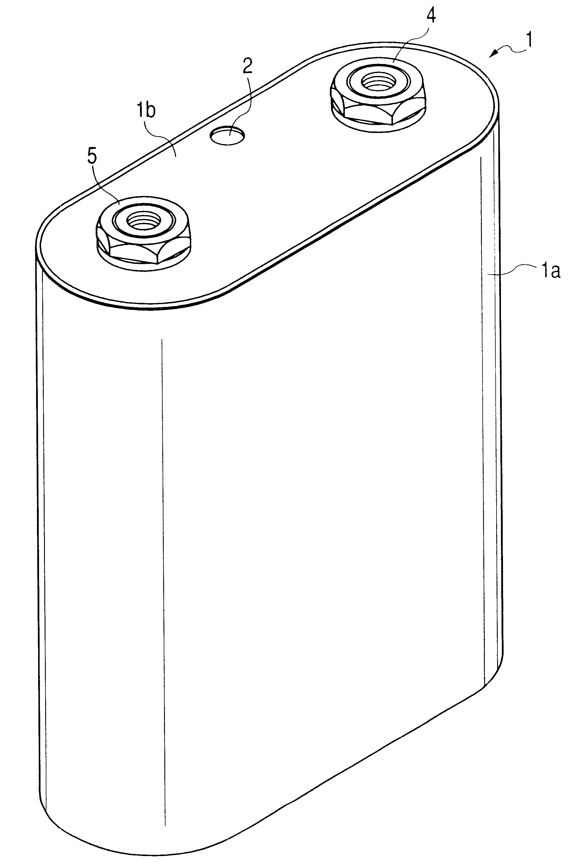
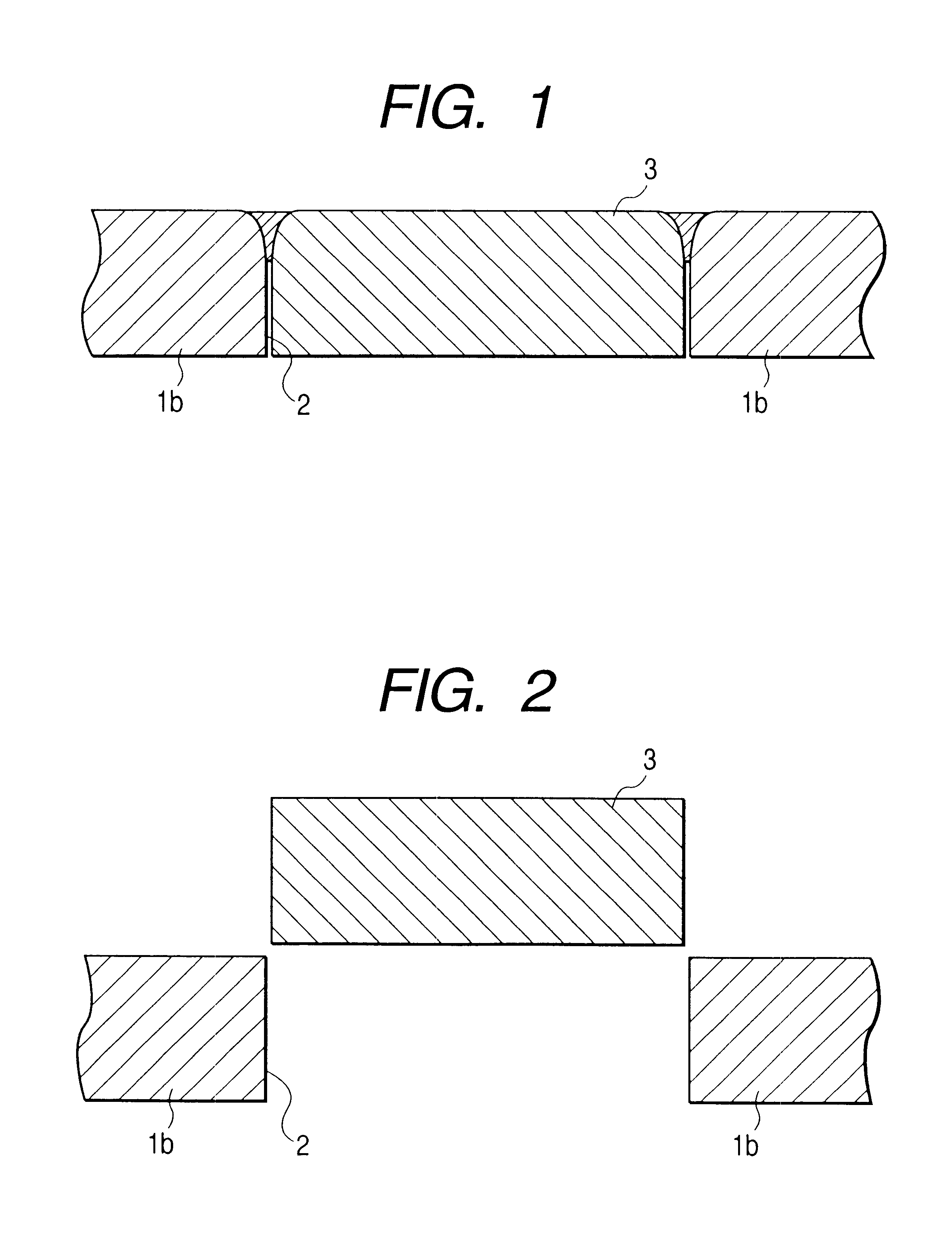
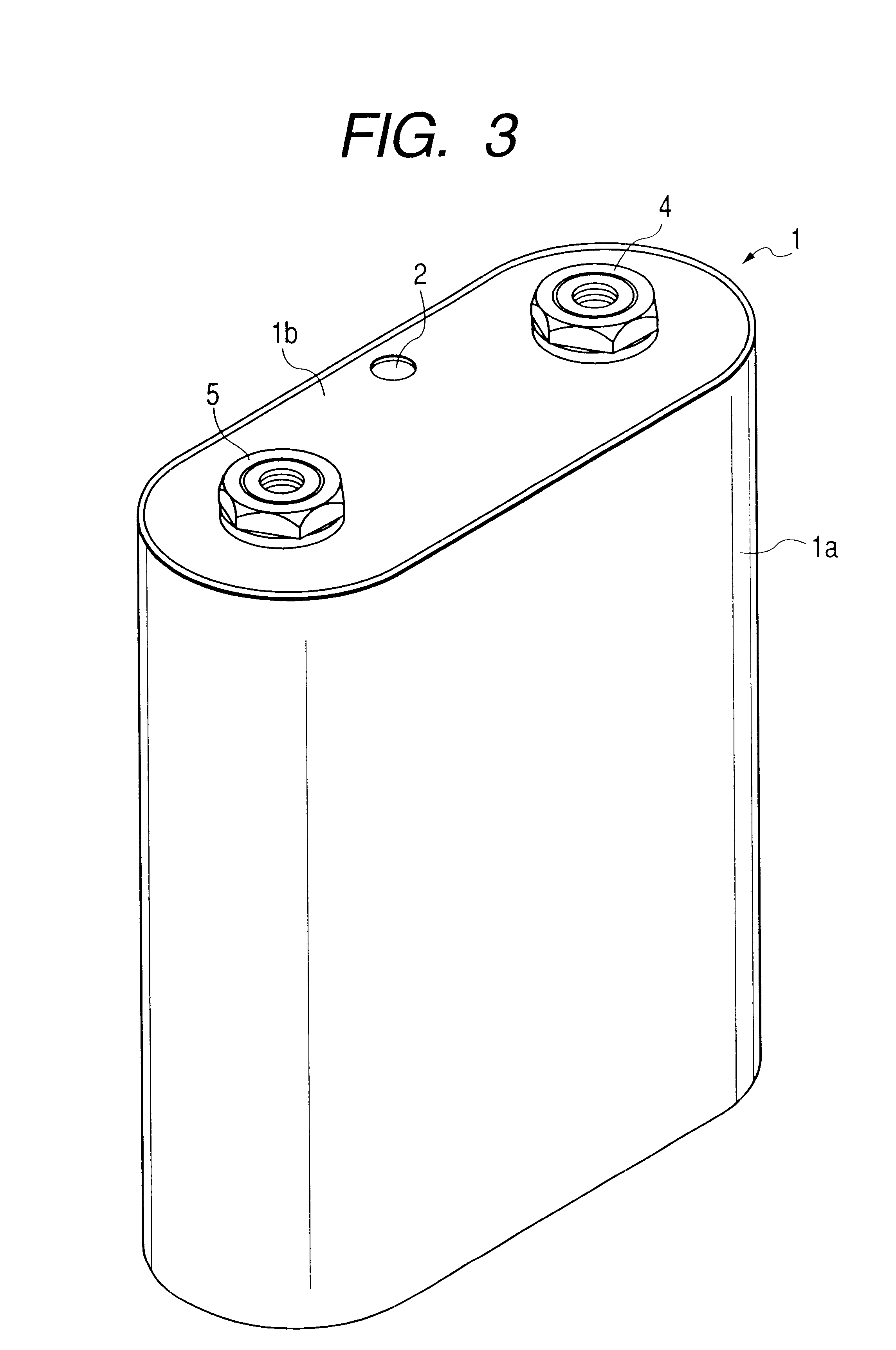
FIGS. 1 to 10 each illustrates an embodiment according to the present invention. FIG. 1 is a partially enlarged vertical sectional view illustrating an embodiment of the present invention showing an electrolyte injecting plug formed laser-welded to an electrolyte injecting port formed on the battery case cover of a non-aqueous electrolyte secondary battery and inserted therein. FIG. 2 is a partially enlarged vertical sectional view illustrating another embodiment of the present invention showing an electrolyte injecting port formed on the battery case cover of a non-aqueous electrolyte secondary battery and an electrolyte injecting plug provided inserted in said electrolyte injecting port. FIG. 3 is an entire perspective view illustrating a further embodiment of the present invention showing the external appearance of a large-sized non-aqueous electrolyte secondary battery. FIG....


PUM

PropertyMeasurementUnit
diameteraaaaaaaaaa
thicknessaaaaaaaaaa
diameteraaaaaaaaaa

Abstract

An electrolyte injecting metallic plug laser-welded to an outer edge of an electrolyte injecting port on a periphery of a battery case. At least a part of the electrolyte injecting metallic plug is inserted into the electrolyte injecting port.

Description

1. Field of the InventionThe present invention relates to a battery such as a non-aqueous electrolyte battery having an electrolyte injecting port formed on a battery case and plugged by an electrolyte injecting plug.2. Description of the Related ArtIn a conventional small-sized non-aqueous electrolyte battery, an aluminum conical electrolyte injecting plug 8 as shown in FIG. 11 is spot-welded to an electrolyte injecting port 2 formed on the battery case 1 through which an electrolyte has been injected into the battery so that the electrolyte injecting plug 8 is welded to the external edge of the electrolyte injecting port 2 to plug the port.However, as the size of the battery increases, the diameter of the electrolyte injecting port 2 must be increased. Consequently, it is made more difficult to spot-weld a large-sized electrolyte injecting plug 8 completely to the electrolyte injecting port 2 leaving no gap therebetween. In order to overcome this difficulty with the conventional n...

Claims


Application Information

Patent Timeline
Patent Type & Authority Patents(United States)
IPC IPC(8): B23K26/28B23K26/00H01M2/36H01M2/00H01M2/04H01M2/02H01M10/36H01M10/40B23K26/21H01M10/05H01M10/0566H01M10/058H01M50/147H01M50/645
CPCB23K26/28H01M2/0426H01M2/043H01M2/361H01M2/365H01M2/0217H01M10/0525Y02E60/10H01M50/103H01M50/169H01M50/147Y02P70/50H01M50/645
Inventor IWATA, MIKIOMATSUO, KAZUMASAINOUE, TAKEFUMIYOSHIDA, HIROAKI
Owner GS YUASA INT LTD
Why Eureka
Try Eureka