Cable connector assembly having an adapter plate for grounding

Inactive Publication Date: 2011-12-15
HON HAI PRECISION IND CO LTD
View PDF4 Cites 46 Cited by
  • Summary
  • Abstract
  • Description
  • Claims
  • Application Information

AI Technical Summary

Benefits of technology

[0007]The second wires are soldered to the adapter plate so as to provide more room

Problems solved by technology

The grounding conductors are soldered to shielding pl

Method used


Image

  • Cable connector assembly having an adapter plate for grounding
  • Cable connector assembly having an adapter plate for grounding
  • Cable connector assembly having an adapter plate for grounding

Examples


Example

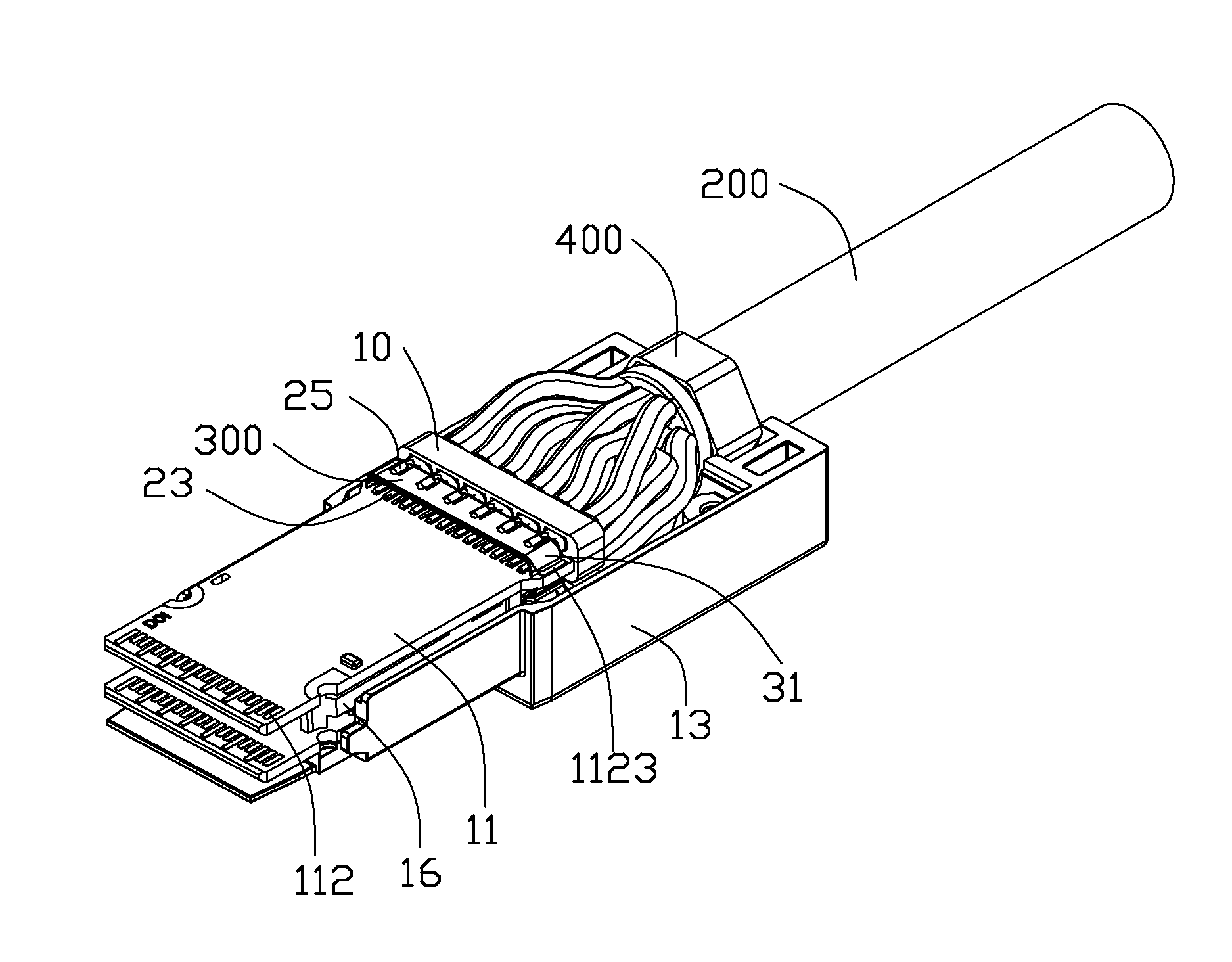
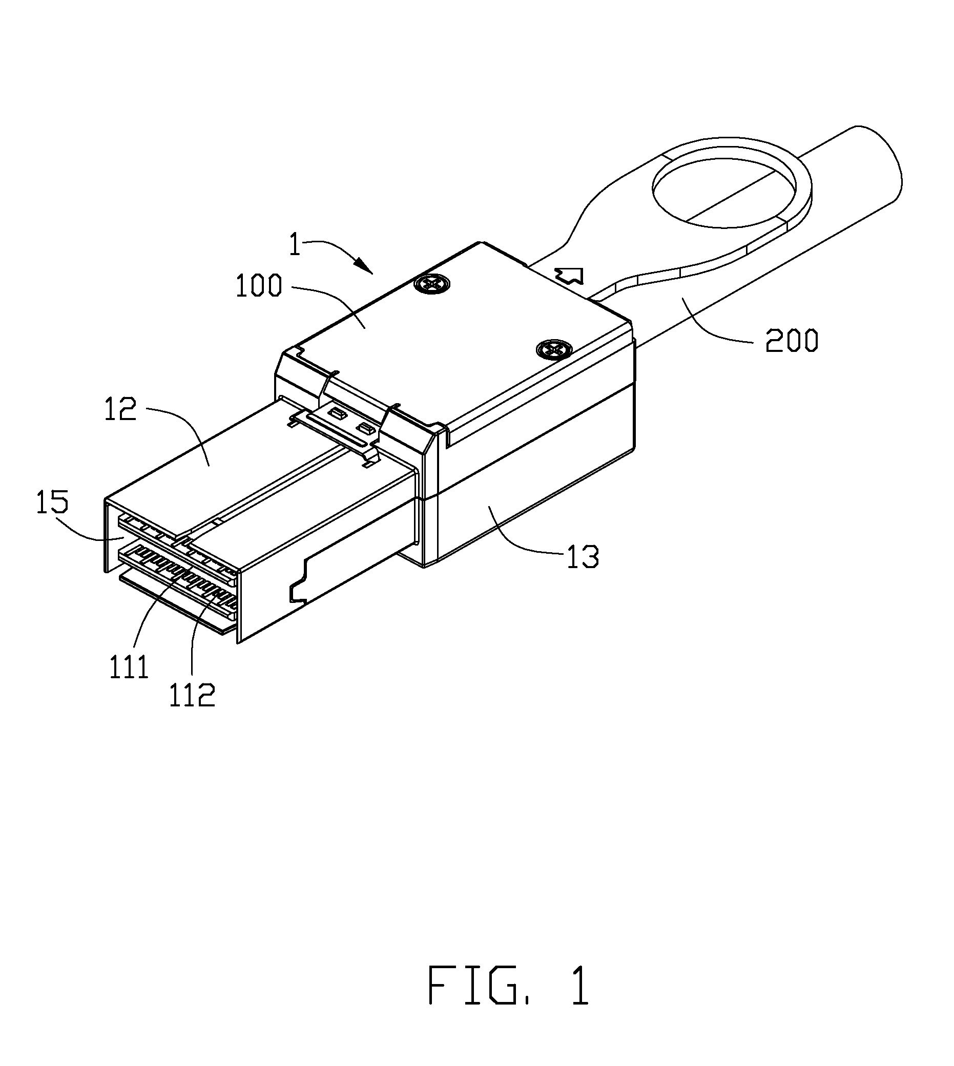
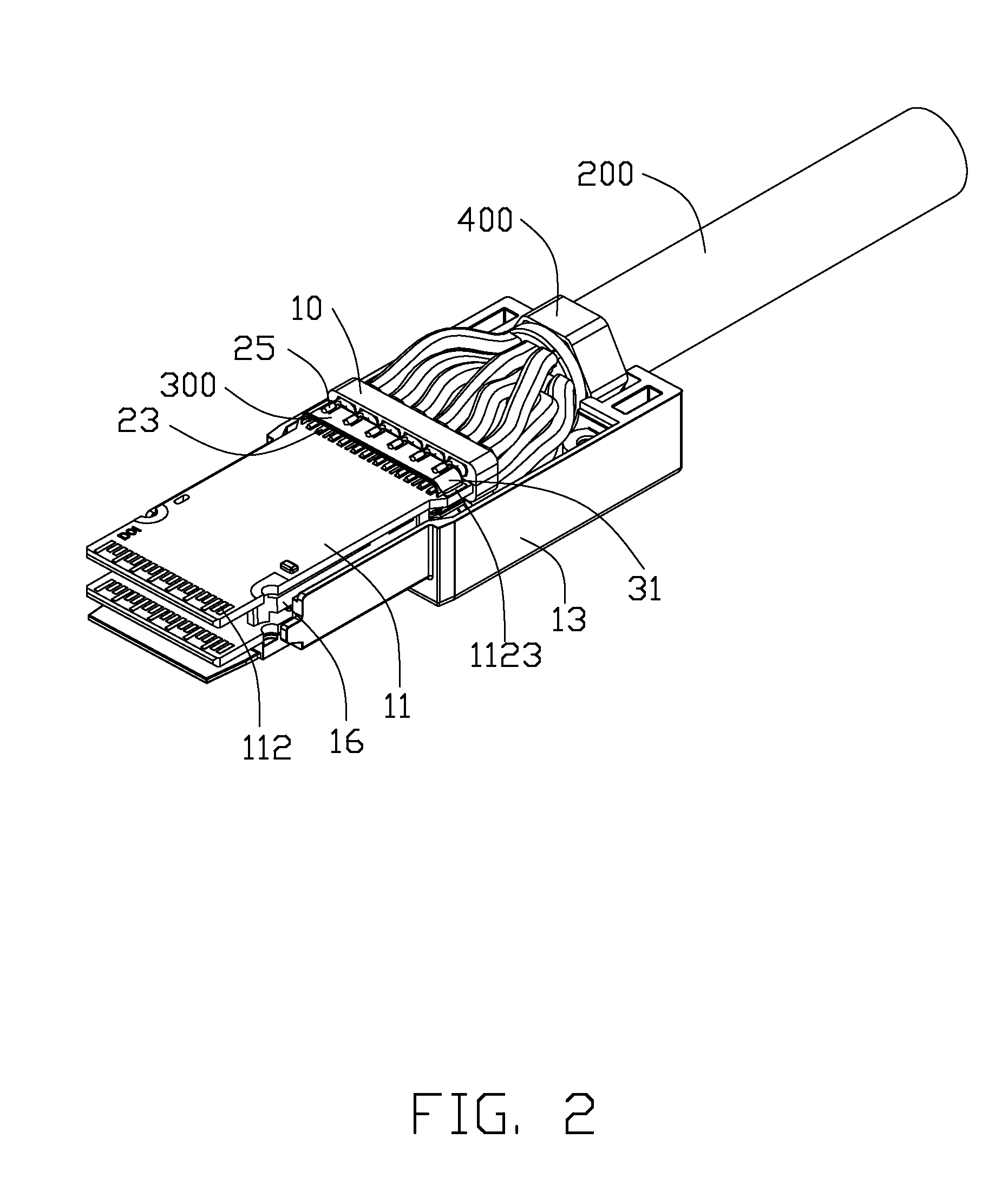
[0016]Reference will now be made to the drawing figures to describe the preferred embodiment of the present invention in detail. Referring to FIGS. 1-6, the present invention provides a cable connector assembly 1 including a connector 100, a cable 200 electrically connected to the connector 100, an adapter plate 300, and a conductive ring 400 assembled between the connector 100 and the cable 200.

[0017]The connector 100 includes a shell, a conductor subassembly 11 received in the shell, and a spacer 10 on the conductor subassembly 11 adjacent to the adapter plate 300. The shell includes a top shell 12 and a bottom shell 13 cooperating with each other to define a holding slot 14 for holding the cable 200 and a receiving room 15 for receiving the conductor subassembly 11 and the cable 200.

[0018]The conductor subassembly 11 comprises a pair of horizontal PCBs (printed circuit boards) 111. Each of the PCBs 111 connects with two adapter plates 300 at opposite sides. Each of the PCBs 111 i...


PUM


Abstract

A cable connector assembly (1) includes a cable (200), a connector (100) including a conductor subassembly (11), and an adapter plate (300). The cable includes a number of wires including a row of first wires (23) and a row of second wires (25). The conductor subassembly (11) has a number of first conductors (1123) and at least one second conductor (1122). The first wires are connected to the first conductors. The adapter plate is disposed between the row of first wires and the row of second wires and includes a conductive layer electrically connecting the second wires to the at least one second conductor.

Description

BACKGROUND OF THE INVENTION[0001]1. Field of the Invention[0002]The present invention relates to a cable connector assembly, and more particularly to a cable connector assembly suitable for use in dense cable wires configuration.[0003]2. Description of Related Art[0004]U.S. Pat. No. 6,685,501 B1 issued to Wu et al. on Feb. 3, 2004 discloses a cable connector comprising a pair of complementary shells, a PCB (printed circuit board) received in the shells, and a cable electrically connected to the PCB. The cable includes a plurality of wires. Each of the wires includes a signal pair and a grounding conductor. The signal pair includes a first signal conductor and a second signal conductor soldered to the top and bottom of the PCB respectively. The cable connector further includes a plurality of shielding plates soldered to the PCB. The grounding conductors are soldered to shielding plates, respectively, which is costly and inconvenient.[0005]Hence, a cable connector assembly having an a...

Claims


Application Information

Patent Timeline
IPC IPC(8): H01R9/03
CPCH01R9/034H01R24/60H01R13/6658H01R13/65914
Inventor ZHANG, XUE-LIANGZHU, QING-MANWANG, CHIEN-CHIUNG
Owner HON HAI PRECISION IND CO LTD
Why Eureka
Try Eureka