Near Infrared Imaging

a technology of infrared imaging and endoscope, which is applied in the field of endoscopes, can solve the problems of limited flexibility, not found wide acceptance, and the doctor is left with no means to view within the patient's body

Active Publication Date: 2013-07-18
STRYKER EUROPEAN OPERATIONS LIMITED
View PDF8 Cites 33 Cited by
  • Summary
  • Abstract
  • Description
  • Claims
  • Application Information

AI Technical Summary

Benefits of technology

[0079]The proximal prisms 31 must have substantially equal path lengths to each detector 33 to yield similar magnifications for such comparisons or superimposed imaging. These proximal prisms 31 could take many forms, but they share approximately equal path lengths per detector and the use of dichroic filters that substantially enhance the optical efficiency or throughput of the system when compared with metalized beam splitter coatings.
[0086]To maximize the lens coupling efficiency to the detector it is important to design the focusing optics and beamsplitting prism assembly to produce a marginal ray angle in the corner of the field which departs from the opto-mechanical axis by 10 or 15 degrees or less from the last optical element in the focusing optics to the detector. It is in this path that the prism assembly 31 is placed. By possessing a shallow marginal ray angle, the ray paths from the various fields within the prism reflect or pass the dichroic filters 31 at a nearly common angle or over a small range of angles. The more similar these angles, the better optical efficiency or throughput for each wavelength range, as dichroic filters by their nature are angle sensitive. Preferably, these angles do not differ from each other by more than 10, 9, 8, 7, 6, 5, 4, 3, 2, or 1 degrees.
[0112]In cases where the reflector is elliptical, the light member will be positioned approximately at the first foci of the ellipse, and the light fiber will be positioned approximately at the second foci which may be reimaged by a condenser lens assembly with a collimated or nearly collimated section between the said condenser lenses. Preferably, an assembly of collimating and focusing lenses is positioned between the member and the light beam splitter to collimate the light directed to beamsplitter 320. The advantage of the above configuration is the creation of near parallel paths of rays, the collimated condition, when intersecting a dichroic coating. The cut on cut off slope of such a coating is steeper if all rays are more or less parallel when interacting with the coating, therefore making it more efficient at dividing a spectrum.
[0119]In some embodiments, additional absorptive filters may be placed between beamsplitter and one or more of the first and second light fibers to further reduce unwanted energy. Locating these filters in this position has several advantages. The first is; there is physically more room than the earlier case where the absorbing filters were located between the first and second foci of the elliptical reflector. The second advantage is also associated with more space, as the beam diameter may be larger than in the converging beam path between the two foci. This results in less flux density on the filter and less substrate heating in the filter. Thirdly, more room results in freedom to use more filters of differing configurations. Fourthly, more room permits the use of thicker more efficient absorptive filters.

Problems solved by technology

There is a class of smaller diameter endoscopes utilizing coherent imaging fibers as relays whose shafts have a limited amount of flexibility, and these devices are commonly called semi-flexible.
There are some commercial applications of directly coupling the camera and optical assemblies included in the shaft mechanism and or coupling mechanism but this has not found wide acceptance, except in Orthopedics for Arthroscopy.
The fear among users has been that if the electronics of the camera fail for some reason then the doctor is left with no means to view within the patient, hence the continuing presence of endoscopes with eyepieces.
Chip-on-a-stick endoscopes usually do not provide a focus means.
However, large diameter flexible endoscopes used in gastroenterology do often have moveable detectors or lenses providing focus.

Method used


Image

  • Near Infrared Imaging
  • Near Infrared Imaging
  • Near Infrared Imaging

Examples


Embodiment Construction

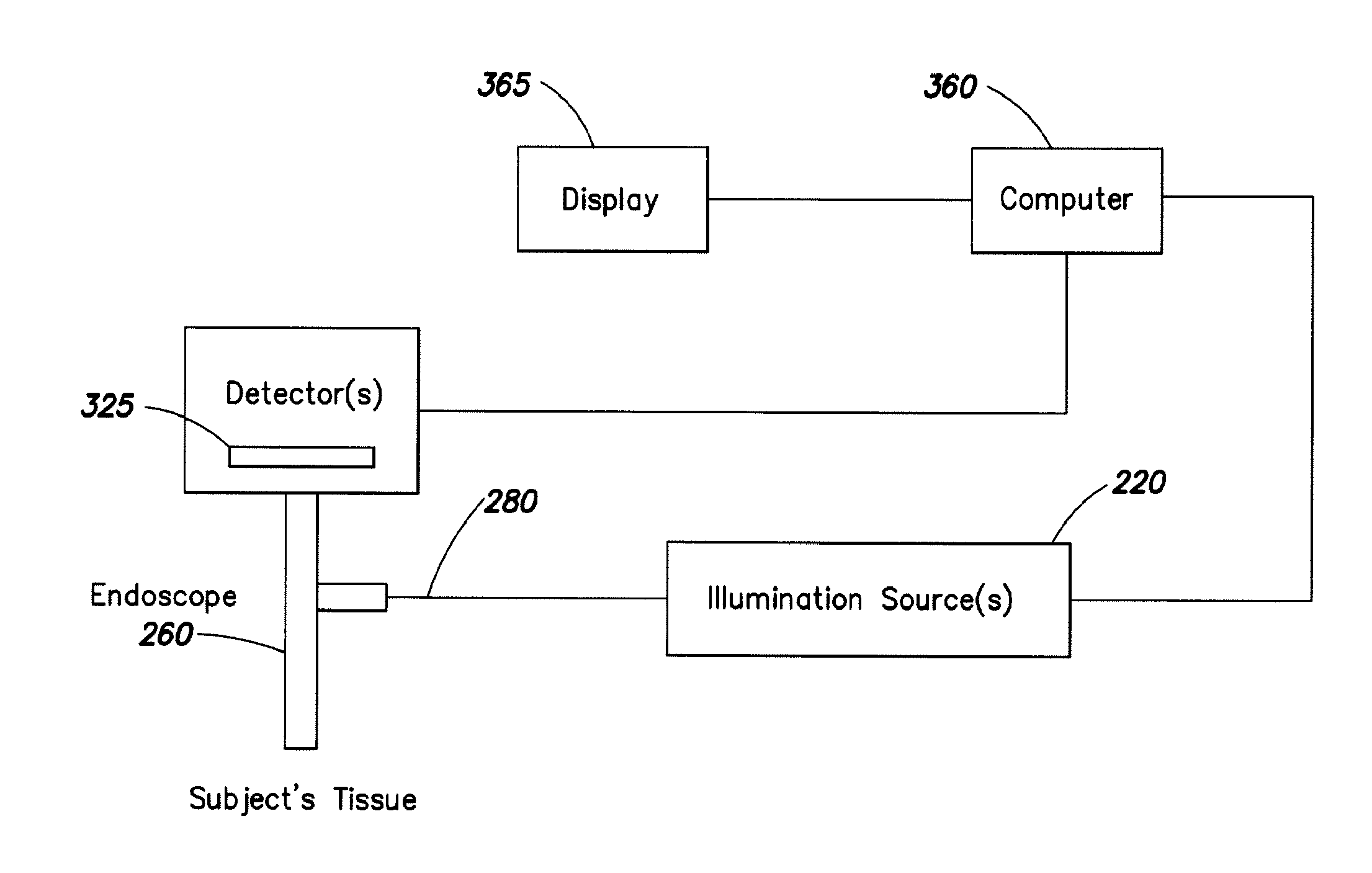
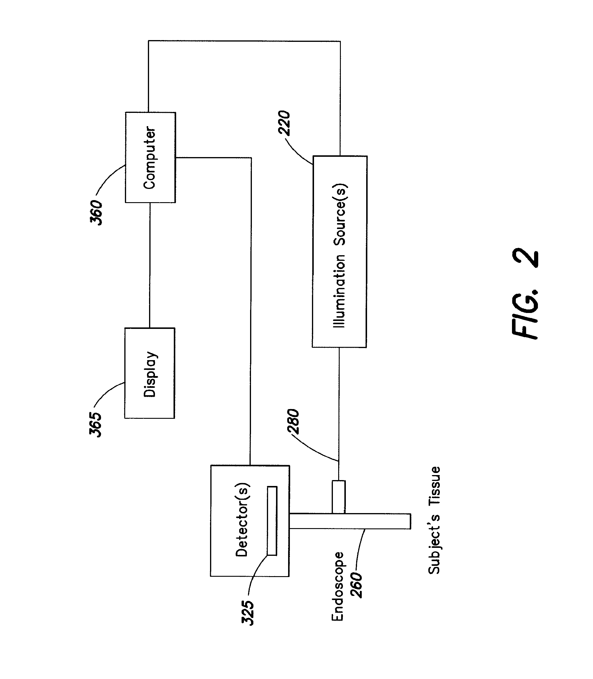
[0033]The invention provides endoscope and wand devices and systems for imaging in the infrared spectrum, and preferably in multiple spectrums at least one of which is infrared. Imaging of fluorescent emissions in the infrared spectrum is particularly difficult because the near infrared light emitted by a fluorescent dye may be an order of magnitude or more lower than the visible light reflected or emitted by a subject. A “device” is any hand-held instrument designed to view or image anatomy, either inside or outside a patient's body.

[0034]In certain embodiments, the invention provides an endoscope or wand device having relay optics such as glasses. The transmitting members have a coating that transmits between about 95% and about 99.5% of energy at a wavelength within the infra red spectrum.

[0035]In some embodiments, the invention provides a prism assembly for separating visible light from infra red light. The prism assembly contains at least one channel configured to receive and t...


PUM

PropertyMeasurementUnit
excitation wavelengthaaaaaaaaaa
excitation wavelengthsaaaaaaaaaa
peak wavelengthaaaaaaaaaa

Abstract

Endoscopes and wands, useful for near infrared imaging, particularly for medical purposes, have transmitting members that transmit between about 95% and 99.9% of the energy at a wavelength within the infrared spectrum. The wands and endoscopes have at least one channel for transmitting and receiving light in the visible spectrum and at least one channel for transmitting and receiving light in the infrared spectrum.

Description

RELATED APPLICATIONS[0001]This application claims priority to U.S. Provisional Application Ser. No. 60 / 771,288 filed on Feb. 7, 2006, and entitled “Endoscopes and Wands”, U.S. Provisional Application Ser. No. 60 / 793,979 filed on Apr. 20, 2006 and entitled “Endoscopes and wands”, and U.S. Provisional Ser. Application No. 60 / 828,627 filed on Oct. 6, 2006 and entitled “Endoscopes and Wands”. Each of these applications is hereby incorporated by reference in its entirety. Each of these are incorporated by reference in their entirety.TECHNICAL FIELD[0002]This application relates to endoscopes and similar devices.BACKGROUND OF THE INVENTION[0003]An endoscope or wand viewing apparatus is usually configured in a way that is well suited for illumination and imaging in visible light.[0004]In this background section endoscopes and wand like devices shall be described in terms of their internal working components. In the second portion of the background section the shortcomings of these predicat...

Claims


Application Information

Patent Timeline
Patent Type & Authority Applications(United States)
IPC IPC(8): A61B5/00A61B1/07A61B1/06
CPCC03C17/3417C03C17/3452G02B5/04G02B23/2453G02B27/1013G02B27/142A61B5/0075H04N5/2256H04N5/33H04N2005/2255A61B1/0661A61B1/07G02B27/145H04N23/555H04N23/56
Inventor TESAR, JOHN C.
Owner STRYKER EUROPEAN OPERATIONS LIMITED
Why Eureka
Try Eureka