Method and Apparatus for Measurement and Control of Temperature for Infused Liquids

Active Publication Date: 2008-08-28
MEDICAL SOLUTIONS
View PDF99 Cites 162 Cited by
  • Summary
  • Abstract
  • Description
  • Claims
  • Application Information

AI Technical Summary

Benefits of technology

[0017]Yet another object of the present invention is to removably secure a temperature sensing device to an IV line and facilitate measurement of fluid temperatures at varying locations along that line.
[0018]Still an

Problems solved by technology

In particular, the Magliochetti et al. and Carter, Jr. et al. systems have size and/or mounting requirements that tend to restrict system application to particular sections of an IV li
nge. This may lead to inaccuracies in fluid temperature control and measurement for the desired sites, thereby risking injury to a pat
Accordingly, these devices are employed for non-sterile applications and are ill-suited for medical applications that require sterility.
Although these devices measure fluid temperature, the devices generally do not provide a displayed temperature to an operator.
Thus, fluids may attain inappropriate temp

Method used


Image

  • Method and Apparatus for Measurement and Control of Temperature for Infused Liquids
  • Method and Apparatus for Measurement and Control of Temperature for Infused Liquids
  • Method and Apparatus for Measurement and Control of Temperature for Infused Liquids

Examples


Embodiment Construction

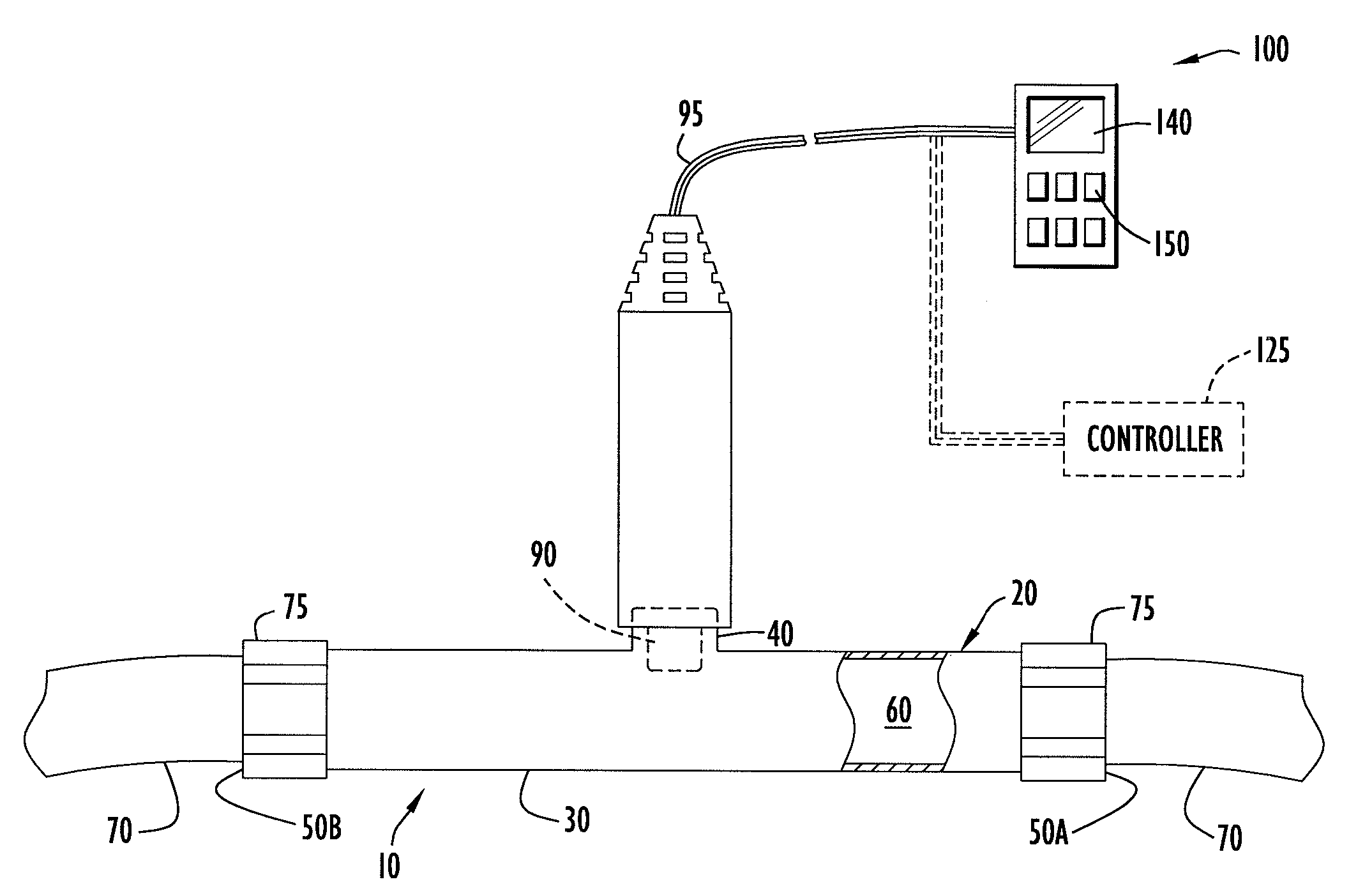
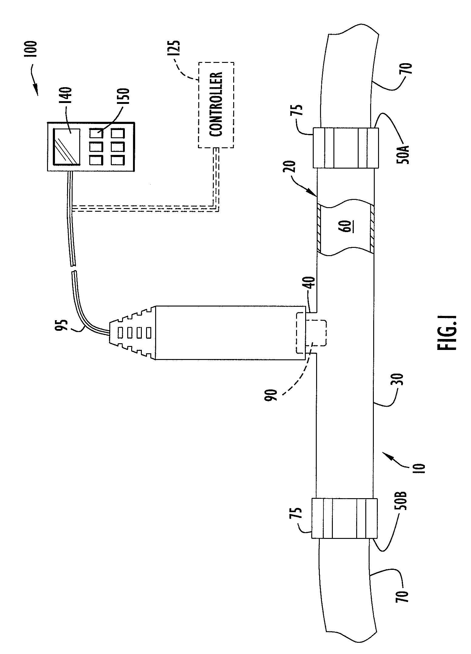
[0039]A temperature sensing device for measuring the temperature of a fluid within an intravenous (IV) or other medical fluid line at desired locations along that line according to an embodiment of the present invention is illustrated in FIG. 1. Specifically, temperature sensing device 10 may be in the form of a fitting 20 including a base portion 30 and a projection 40 extending transversely from an intermediate section of the base portion. By way of example only, the fitting includes a T-type configuration; however, any suitable configuration (e.g., a Y-type fitting, cross fitting, coupling, etc.) may be utilized. Base portion 30 is substantially cylindrical with a first open end 50A, a second open end 50B, and a channel or fluid conduit 60 defined longitudinally through the base portion to permit fluid flow through the fitting. Base portion channel 60 preferably includes generally uniform dimensions; however, the channel dimensions may vary along the channel (e.g., the channel di...


PUM


Abstract

A device according to present invention embodiments measures the temperature of fluid within an IV line at selected locations. The device may be in the form of a fitting including a projection in fluid communication with a fluid channel to receive a temperature sensor. A thermally conductive receptacle may be disposed in the projection to receive the temperature sensor and partially extends into the fluid channel for contact with the fluid. The temperature sensor may be coupled to a temperature display device and/or controller to display the measured temperature and/or control a thermal element to regulate fluid temperature. The fitting may further include a looped configuration and/or a control valve that controls the flow of fluid through the fluid channel. In addition, the device may further be connected to, or be in the form of, a needle hub to measure fluid temperature proximate the entry site on a patient.

Description

BACKGROUND OF THE INVENTION[0001]1. Technical Field[0002]The present invention pertains to temperature sensing devices, such as the types of temperature sensing devices disclosed in: U.S. patent application Ser. No. 10 / 849,251, entitled “Temperature Sensing Device for Selectively Measuring Temperature at Desired Locations Along an Intravenous Fluid Line” and filed May 20, 2004, now U.S. Patent Application Publication No. 2004 / 0249336 (Faries, Jr. et al.); U.S. Pat. No. 7,090,658 (Faries, Jr. et al.); and U.S. Pat. No. 6,824,528 (Faries, Jr. et al.). The disclosures of the foregoing patents and patent application publication are incorporated herein by reference in their entireties. In particular, the present invention pertains to devices that monitor temperature of an intravenous fluid at any desirable location along a fluid line (e.g., an intravenous (IV) fluid line) and may further selectively enable and / or disable the flow of fluid through those devices to ensure a desired fluid t...

Claims


Application Information

Patent Timeline
IPC IPC(8): G01K13/02A61M1/00
CPCA61M5/445G01K2013/026G01K1/146A61M2205/3368G01K13/026
Inventor FARIES, DURWARD I.HEYMANN, BRUCE R.BLANKENSHIP, CALVINHENDRIX, DAVID
Owner MEDICAL SOLUTIONS
Why Eureka
Try Eureka