Patient Monitoring System

Inactive Publication Date: 2014-09-18
NOVA TECH CORP
View PDF5 Cites 0 Cited by
  • Summary
  • Abstract
  • Description
  • Claims
  • Application Information

AI Technical Summary

Benefits of technology

This patent aims to provide an affordable and easy-to-use patient monitoring device that can measure physiological parameters and record visual observations for transfer to a medical facility. It is designed to improve the accuracy and efficiency of patient care and facilitate the delivery of medical information.

Problems solved by technology

Unfortunately the advantages of a hospital environment with its resources and personnel do not exist at many trauma sites, for example, those at typical accident scenes or at battlefield sites.
Moreover, typically no information is recorded about the patient during initial treatment and transport to a field hospital.
The sensor band is disposable and has a limited life.
Each of these proposals requires the use of bulky equipment so it is difficult to maintain an inventory for multiple patients.
It is not likely that such a harness would be an acceptable alternative for application to a trauma patient on a battlefield or at another trauma site.
In addition, medical personnel may have the additional burden of placing the harness on a trauma patient under adverse circumstances.
They are not always available at a trauma site or on the battlefield.
The use of smart cards or memory cards as suggested in the Ferguson et al. patent present problems because such devices are prone to being lost at a trauma site or during patient transport to a hospital or other central site.
The amount of data about a patient that is conveyed from the trauma site to a medical facility with this patient monitoring system, although increased over information available by prior apparatus, is somewhat limited.
However, often time constraints imposed by a particular situation prevent a medic from recording such observations in a form that is easily conveyed to a remote medical facility.
Consequently the information resulting from a medic's visual observation is lost because it is not communicated to other medical personnel at a remotely located medical center.

Method used


Image

  • Patient Monitoring System
  • Patient Monitoring System
  • Patient Monitoring System

Examples


Embodiment Construction

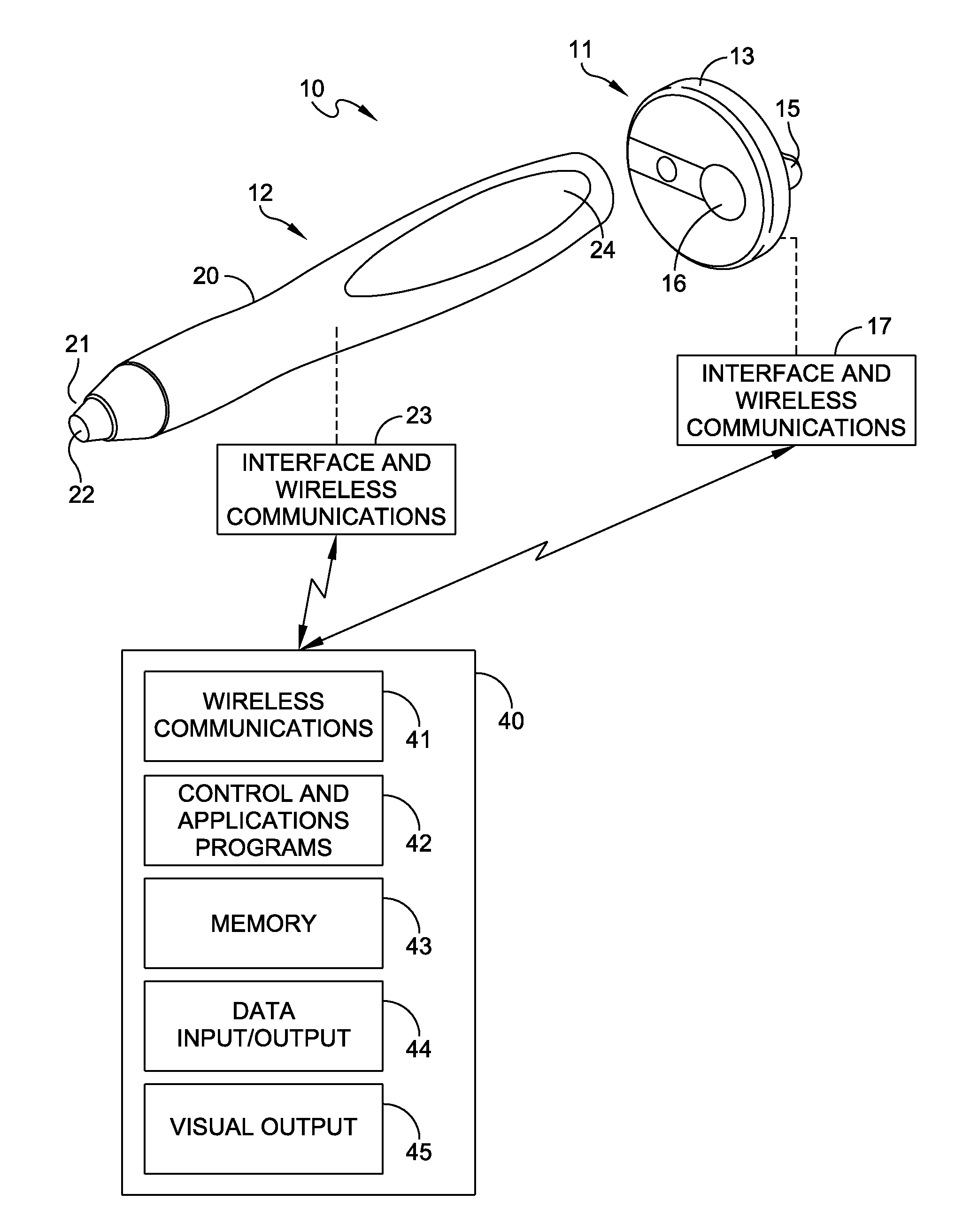
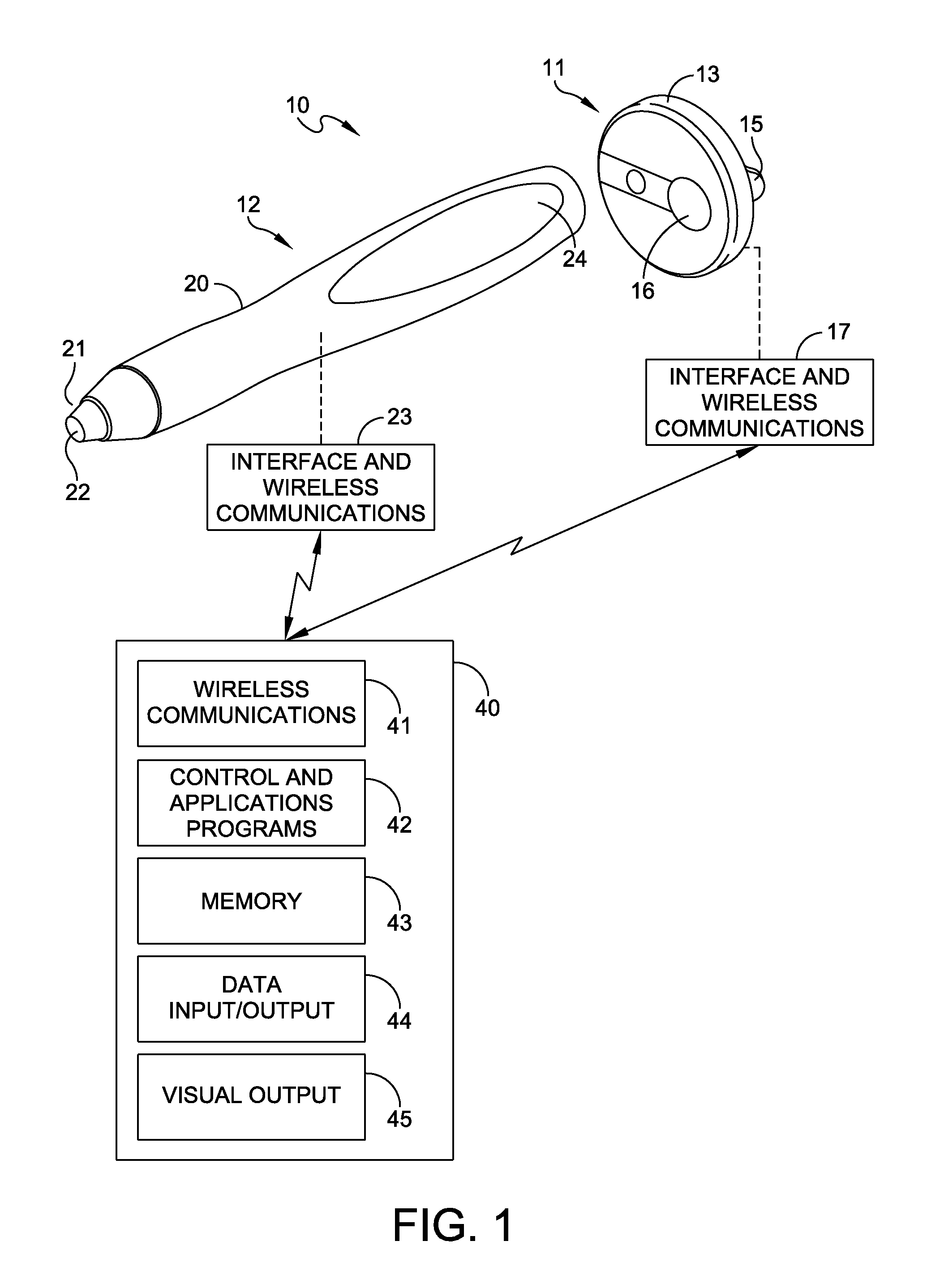
[0024]FIG. 1 discloses a patient monitoring apparatus 10 with a separate sensor button-like device that records data related to at least one medical parameter, hereinafter a “sensing-recording device 11” and a portable probe 12. In use, a medic attaches a single sensing-recording device 11 to a single patient from an inventory carried by the medic. In the following discussion the term “medic” normally identifies military personnel; however, in conjunction with this invention the term includes both military personnel and civilian personnel such as an EMT. Each medic will also have a single probe 12 which will interact with any proximate sensing-recording device, such as the sensing-recording device 11.

[0025]As described in the above-identified U.S. Pat. Pub. 2006 / 0036137, the sensing-recording device 11 includes a base unit 13, a clip having a transfer portion and a clip arm 15 spaced and essentially parallel to the housing 13. The housing 13 also carries an on / off button 16 and an i...


PUM


Abstract

A patient monitoring system including a sensing-recording device that attaches to a patient, a probe utilized to attending personnel at a trauma site and a portable data processing system with wireless communications means with each of said probe and sensing-recording device. A medic utilizes a portable data processing device in the form of a tablet or smart phone to select measurements and to control the operation of the probe and the sensing-recording device. Information obtained from the probe can be transferred to the sensing-recording device. The sensing-recording device includes sensors for continuing to accumulate information about various physiological parameters during the transport of a patient from a trauma site to a medical facility.

Description

CROSS-REFERENCE TO RELATED APPLICATION[0001]Reference is made to U.S. app. Ser. No. 11 / 161,688 filed Aug. 12, 2005 for a Patient Monitoring Device and published Feb. 16, 2006 as U.S. Pat. Pub. No. 2006 / 0036137 which is incorporated by reference in its entirety herein.[0002]This application claims priority from U.S. Provisional Patent Application Ser. No. 61 / 791,900 filed Mar. 15, 2013 for an Improved Patient Monitoring System which is incorporated by reference in its entirety herein.BACKGROUND OF THE INVENTION[0003]1. Field of the Invention[0004]This invention generally relates to monitoring physiological parameters of a patient and more specifically to the monitoring of such parameters in patients who are geographically remote from a medical facility.[0005]2. Description of Related Art[0006]Monitoring of a patient's physiological parameters in a medical environment is an important element of patient diagnosis and treatment. Within a modern medical facility, such as a hospital, such...

Claims


Application Information

Patent Timeline
IPC IPC(8): A61B5/00A61B5/332
CPCA61B5/0013A61B5/0022A61B5/002A61B5/0077A61B5/02055A61B5/0531A61B5/14551G16H40/67
Inventor CAMPBELL, MICHAEL J.E.
Owner NOVA TECH CORP
Why Eureka
Try Eureka