Pressure Measurement Device and Method

Inactive Publication Date: 2015-04-23
BILLETT RONALD
View PDF7 Cites 2 Cited by
  • Summary
  • Abstract
  • Description
  • Claims
  • Application Information

AI Technical Summary

Benefits of technology

The patent describes a method for measuring pressure inside a deformable vessel containing a compressible gas. The pressure is transferred from the vessel to an external chamber through a flexible membrane covering a window in the chamber. The pressure transfer is effectuated by either pressing the vessel against the chamber or the reverse. The transferred pressure is then measured using a traditional gauge or other available pressure sensor. A calibration process is used to ensure accurate measurement when the deformable vessel flattened area is equal to the area of the chamber diaphragm. Various mechanisms are used to limit the extent that the vessel and chamber are pressed together to prevent inaccurate measurement. The patent provides a technical solution for measuring pressure in deformable vessels.

Problems solved by technology

This is required as beyond a limited amount of external pressure against the deformable vessel, the pressure inside the vessel will increase, and the measured pressure from the chamber will be an inaccurate measurement of the pressure inside the vessel in its resting condition.

Method used


Image

  • Pressure Measurement Device and Method
  • Pressure Measurement Device and Method
  • Pressure Measurement Device and Method

Examples


Embodiment Construction

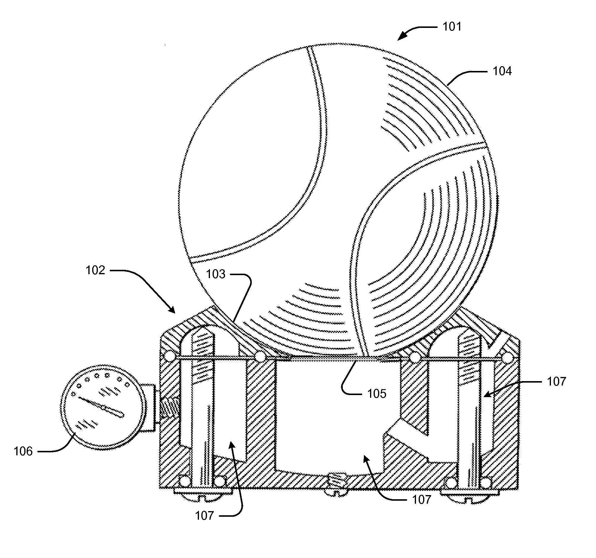
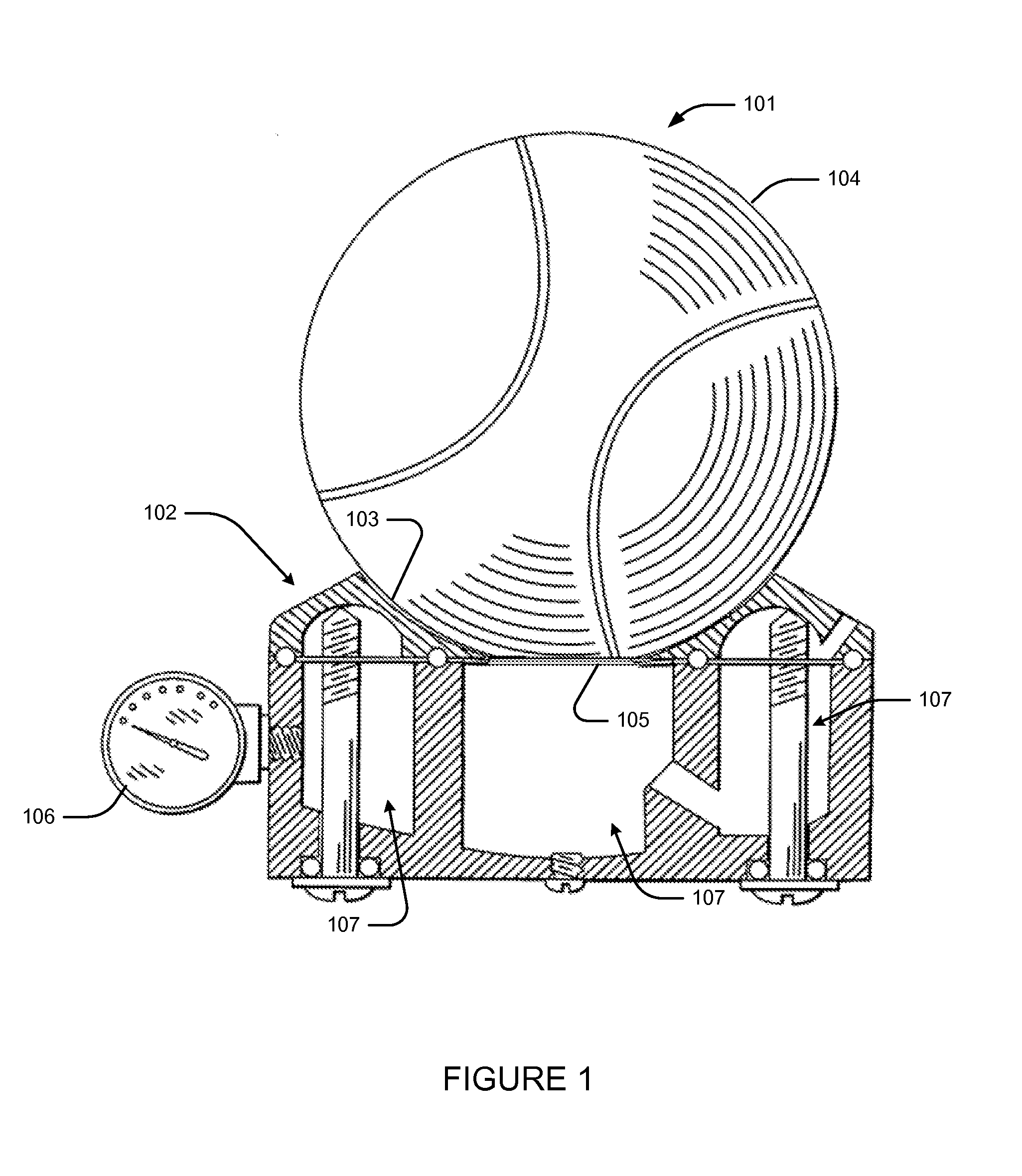
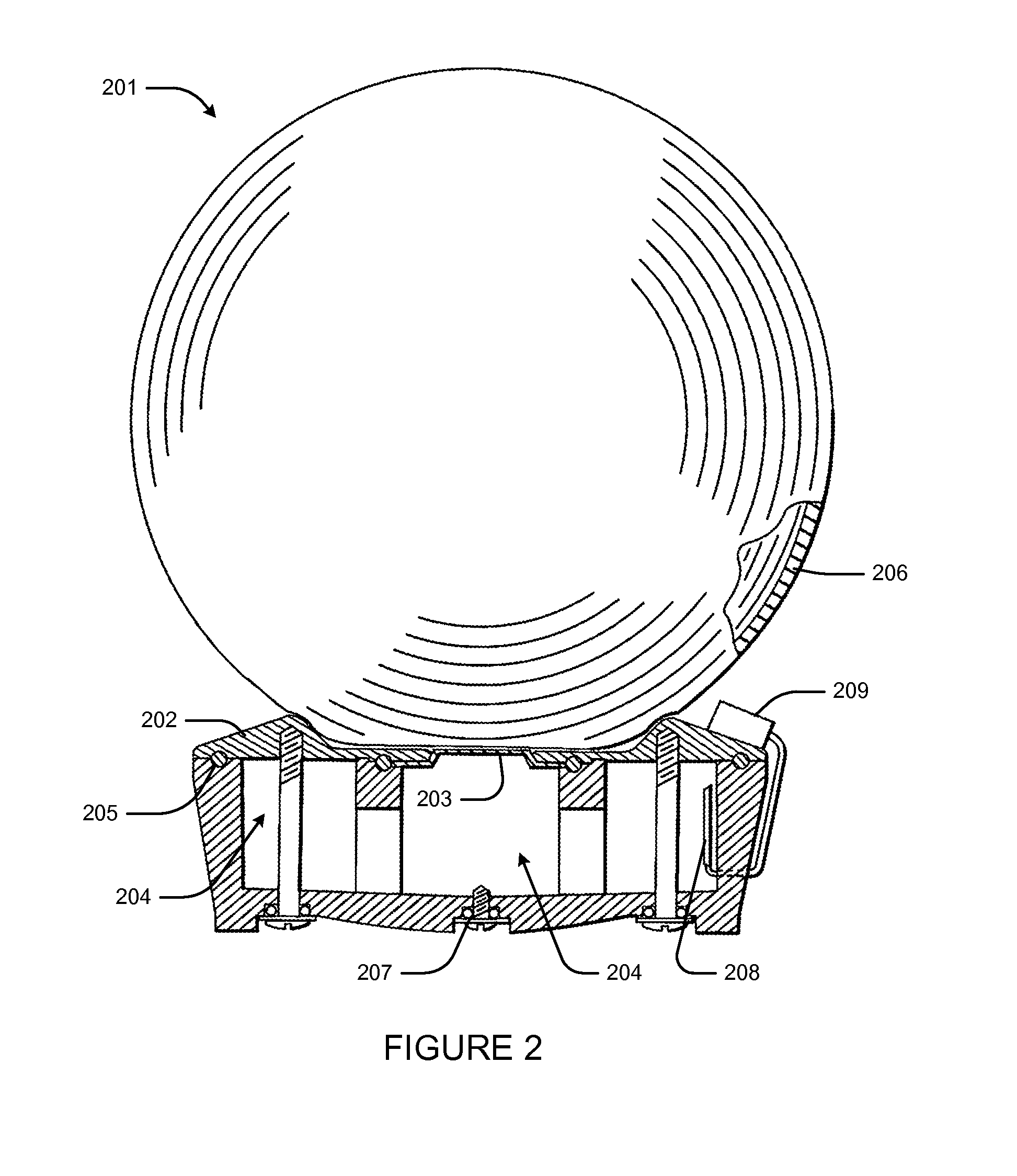
[0013]In certain embodiments as shown in FIG. 1, the sealed deformable vessel may be a ball such as a tennis ball 101. The pressure transfer and measurement apparatus 102 is situated underneath the ball, which is pressed into the upper spherical cupped receiving surface 103. The shape of the solid receiving portion of the apparatus 103 and the diameter of the deformable diaphragm 105 are determined according to the deformability or elastic properties of the outside wall of the vessel 104. As the deformable pressurized ball in pressed into the device against the diaphragm, the air pressure within the ball is transferred across the flattening diaphragm 105 to the incompressible fluid in the chamber 107. The rising pressure inside the vessel is measured in certain embodiments by various sensors or gauges such as a mechanical dial gauge 106 as shown in FIG. 1. The apparatus is designed with an optimized volume of incompressible fluid which is contiguous throughout the device which conta...


PUM


Abstract

Disclosed is a device and method for measuring pressure inside a deformable vessel containing a compressible gas, by the transfer of pressure inside the vessel to a primarily rigid chamber external to the vessel through a flexible membrane covering a window in the chamber, which is filled with a suitable incompressible fluid. The pressure transfer is effectuated by either pressing the vessel against the chamber or the reverse. The transferred pressure is then measured by a traditional gauge or other available pressure sensor. Depending on the elasticity of the vessel exterior wall, a fixed area for compressing a flat area of the vessel exterior wall and transfer membrane is chosen. At this chosen amount of deformation, the pressure differential between the vessel interior and the exterior chamber is zero, facilitating the external measurement of the vessel internal gas pressure.

Description

FIELD OF THE INVENTION[0001]The present invention is generally related to the field of pressure measurement.BACKGROUND OF THE INVENTION[0002]Pressure measurement has a history which begins in the seventeenth century Italian Renaissance with the invention of the barometer. The contemporaneous understanding of atmospheric air pressure fundamentally changed the mechanical understanding of how air exerts pressure against the human body and vessels. In the following centuries, a variety of mechanical and electrical devices would be used to measure pressure, from the first mechanical barometer, the aneroid barometer invented in 1843, to piezoresistive silicon sensors used in some modern smart phones.[0003]One particular pressure measurement application remains problematic, namely measuring pressure inside a sealed deformable vessel. Two longstanding specific applications of this type include the tennis ball and the human eye.[0004]In the case of a tennis ball, since the balls have no valv...

Claims


Application Information

Patent Timeline
IPC IPC(8): G01N7/00A61B3/16G01L9/00
CPCG01N7/00A61B3/16G01L9/008G01L17/005G01L19/16G01L27/002
Inventor BILLETT, RONALD
Owner BILLETT RONALD
Why Eureka
Try Eureka