System for inductive power transfer

a technology of inductive power transfer and synchronous system, which is applied in the direction of battery data exchange, exchanging data chargers, transportation and packaging, etc., can solve the problems of reducing affecting the efficiency of the primary coil's power transfer to the secondary coil, etc., to achieve sufficient operation of the device, reduce the undesired electromagnetic emissions generated power signal and the primary lc circui

Inactive Publication Date: 2008-10-02
VISTEON GLOBAL TECH INC
View PDF16 Cites 256 Cited by
  • Summary
  • Abstract
  • Description
  • Claims
  • Application Information

AI Technical Summary

Benefits of technology

[0007]Not only does the resonance control module seek the resonant frequency to operate the primary LC circuit at or as close as possible to its natural resonance, the primary unit includes the synchronous drive system that controls the magnitude of a power signal used to power the primary LC circuit. Accordingly, the magnitude of the power signal can be adjusted to efficiently transfer power to a device to sufficiently operate the device and / or charge a battery without substantial frequency variations. Additionally, undesired electromagnetic emissions generated by the power signal and emitted by the primary LC circuit are reduced.

Problems solved by technology

One problem with inductive power transfer is the lack of spatial freedom between the primary coil and the secondary coil.
The efficiency at which the primary coil transfers power to the secondary coil is limited by the distance between the primary unit and the device, including the secondary unit.
However, adjusting frequency to operate at resonance and simultaneously controlling amplitude can be problematic.
Additionally, using voltage pulses to control the resonance frequency and amplitude can easily generate undesired electromagnetic emissions when inductively coupling a primary coil to a secondary coil.
Furthermore, primary and secondary coils intended to couple with a high degree of spatial freedom can easily radiate unwanted electromagnetic energy due to the pulsing form of the control, especially if the secondary coil includes a rectifier circuit having sudden changes in current flowing through the secondary coil.

Method used


Image

  • System for inductive power transfer
  • System for inductive power transfer
  • System for inductive power transfer

Examples


Embodiment Construction

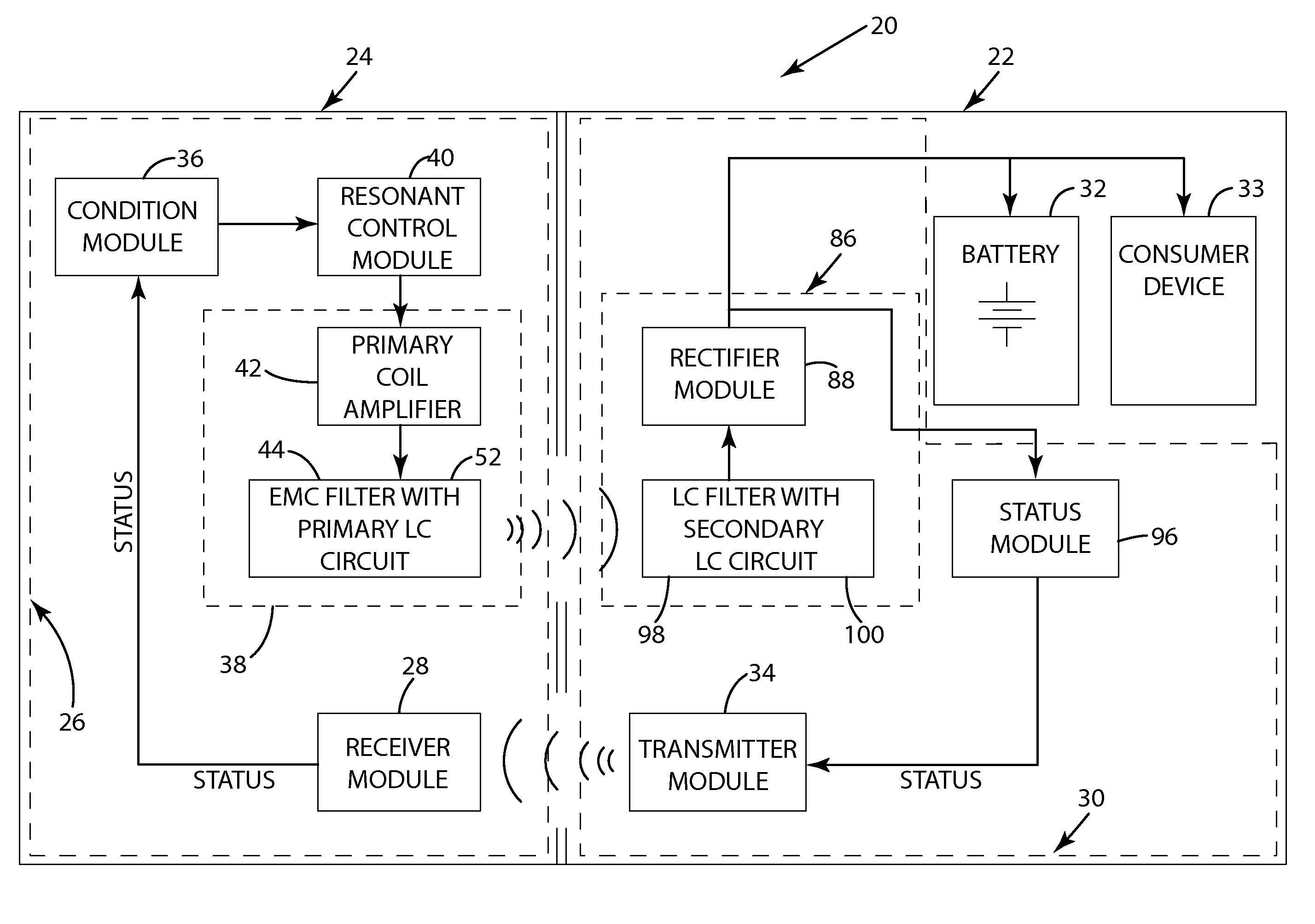
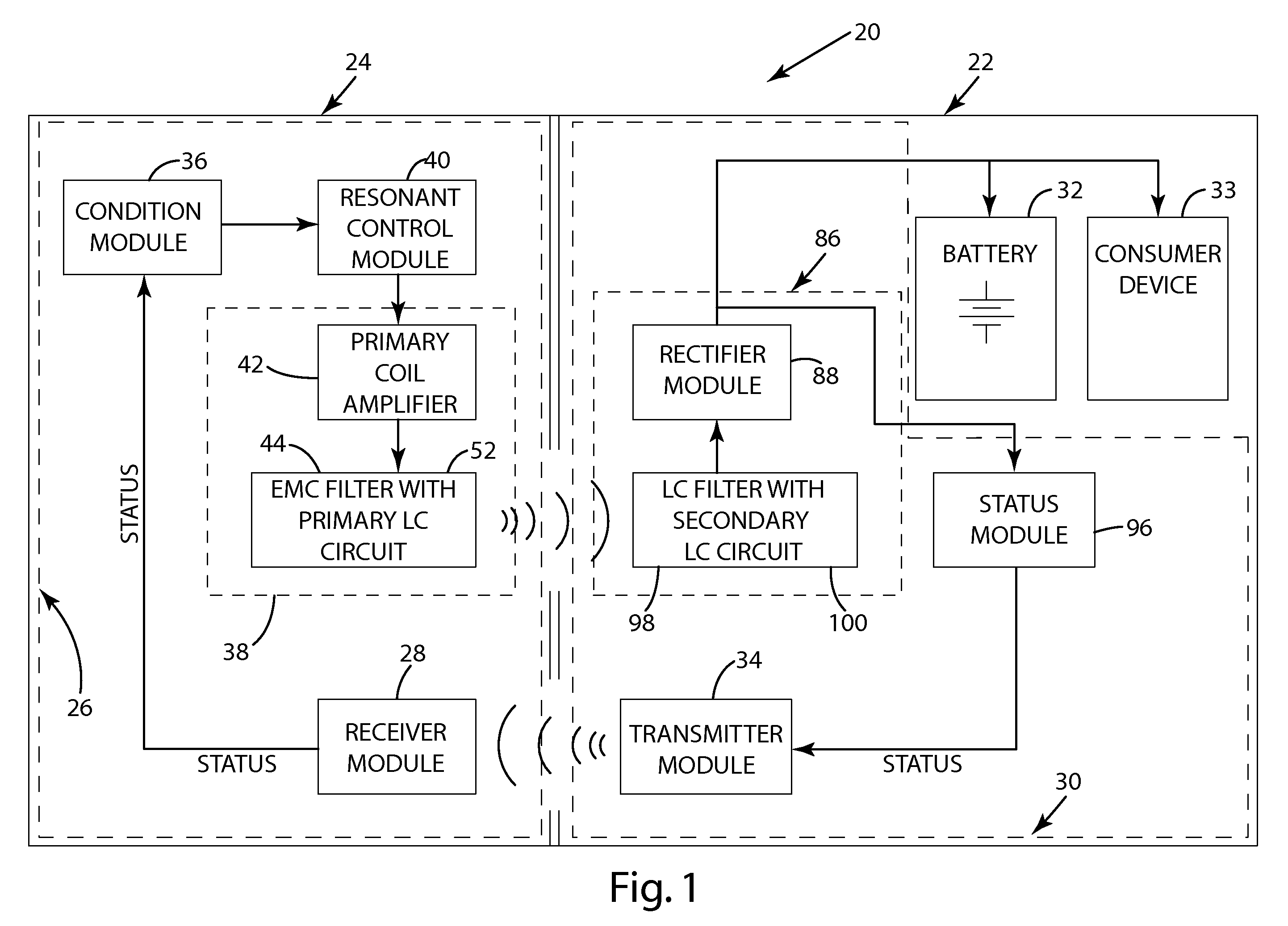
[0013]Referring to the Figures, wherein like numerals indicate corresponding parts throughout the several views, an inductive power transfer system is generally shown for adjusting the conduction angle of an oscillating circuit. Referring to FIG. 1, the inductive power transfer system 20 includes a primary unit 24 and a secondary unit 22. The primary unit 24 includes a synchronous drive system 26 and the secondary unit 22 includes a secondary receiving system 30. The synchronous drive system 26 inductively powers the secondary receiving system 30, as discussed in greater detail below. The synchronous drive system 26 may further include a receiver module 28 that communicates with the secondary receiving system 30 to receive a status signal (STATUS) indicating power conditions within the secondary unit 22. The secondary unit 22 may include a battery 32 and / or a consumer device that can be charged and / or powered by the secondary receiving system 30. The secondary unit 22 may further in...


PUM


Abstract

An inductive power transfer system including a synchronous drive system having a resonance control module. The resonance control module includes a primary coil module with a primary LC circuit. The resonance control module seeks and detects the resonant frequency of the primary LC circuit. The synchronous drive system further includes a switching coil amplifier for selectively energizing the primary coil to keep the primary LC circuit operating at or as close as possible to its natural resonant frequency. The inductive power transfer system may further include a secondary receiving unit. The secondary receiving unit includes a secondary LC circuit coupled with the primary LC circuit for inductively receiving power. The secondary LC circuit includes an LC filter and a rectifier unit for operating the secondary LC circuit at a mutual resonance with the primary LC circuit.

Description

BACKGROUND OF THE INVENTION[0001]1. Field of the Invention[0002]The subject of the invention relates to an inductive power transfer system and more specifically to a synchronous system for inductively transferring power.[0003]2. Description of the Prior Art[0004]Inductive power transfer can be used to power a device and / or charge a remotely located battery without the need for any electrical connection between the device and a power source. Inductive power transfer typically uses a primary coil and a secondary coil. The primary coil may be contained within a primary unit or source connected to an AC (Alternating Current) power source. The secondary coil may be contained in a secondary or receiving system, which may be directly included in, for example a cordless consumer device. When the cordless device is placed near the primary unit, such that the primary coil is in proximity to the secondary coil, power is inductively transferred from the primary coil to the secondary coil. The e...

Claims


Application Information

Patent Timeline
Patent Type & Authority Applications(United States)
IPC IPC(8): H02J7/00
CPCH02J7/025H02J50/80H02J50/10H02J7/00034H02J50/70H02J50/12H02J7/00
Inventor WEBER, CHARLES F.GREEN, BRUCE S.CLARK, CT THOMASRICHLIE, CHARLIE A.TKACZYK, GARY
Owner VISTEON GLOBAL TECH INC
Why Eureka
Try Eureka