Power transfer system and power transfer method

a technology of power transfer system and power transfer method, applied in the direction of navigation instruments, high-level techniques, instruments, etc., to achieve the effect of efficiently transferring power therebetween

Active Publication Date: 2017-03-16
MITSUBISHI ELECTRIC CORP
View PDF0 Cites 10 Cited by
  • Summary
  • Abstract
  • Description
  • Claims
  • Application Information

AI Technical Summary

Benefits of technology

[0013]The power transfer system according to the present invention is a power transfer system in a vehicle that can travel on power, the system including: an information obtaining unit that obtains possible driving distance information indicating a possible driving distance of each of vehicles that travel to a same destination; and a power transfer controller that controls, based on the possible driving distance information obtained by the information obtaining unit, transfer of power between a power-surplus vehicle with extra power and a power-shortage vehicle lacking in power so that the vehicles can reach a same charging station, the power-surplus vehicle and the power-shortage vehicle being included in the vehicles. Thus, the power transfer system enables the vehicles that travel in a group to efficiently transfer power therebetween.
[0014]Furthermore, the power transfer method is a method for transferring power in a vehicle that can travel on power, the method including: obtaining possible driving distance information indicating a possible driving distance from each of vehicles that travel to a same destination; and controlling, based on the obtained possible driving distance information, transfer of power between a power-surplus vehicle with extra power and a power-shortage vehicle lacking in power so that the vehicles can reach a same charging station, the power-surplus vehicle and the power-shortage vehicle being included in the vehicles. Thus, the power transfer method enables the vehicles that travel in a group to efficiently transfer power therebetween.
[0015]The object, features, aspects and advantages of the present invention will become more apparent from the following detailed description and the accompanying drawings of the present invention.

Problems solved by technology

Furthermore, the surplus-power vehicle with extra power means a vehicle having additional power other than the power necessary to travel up to a predetermined point, whereas the power-shortage vehicle lacking in power means a vehicle that does not have power necessary to travel up to a predetermined point.

Method used


Image

  • Power transfer system and power transfer method
  • Power transfer system and power transfer method
  • Power transfer system and power transfer method

Examples


embodiment 1

[0044]First, a configuration of a power transfer system in a vehicle that can travel on power according to Embodiment 1 of the present invention will be described. Embodiment 1 and the following Embodiments each will describe a power transfer system implemented by a power transfer apparatus alone.

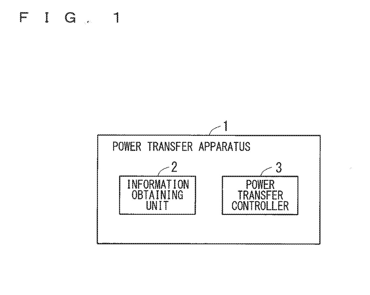
[0045]FIG. 1 is a block diagram illustrating an example of a configuration of a power transfer apparatus 1 according to Embodiment 1. FIG. 1 illustrates the minimum constituent elements necessary to construct the power transfer apparatus 1.

[0046]As illustrated in FIG. 1, the power transfer apparatus 1 includes at least an information obtaining unit 2 and a power transfer controller 3.

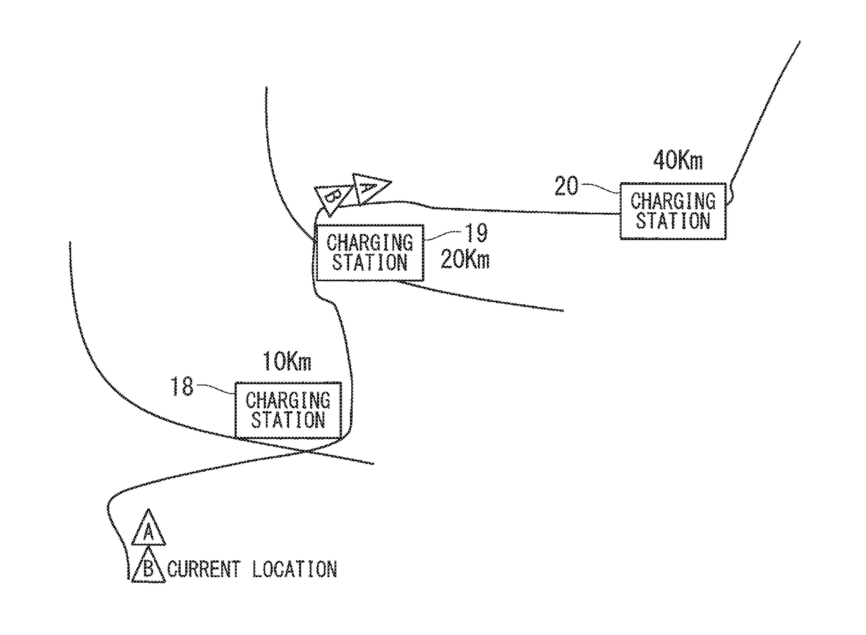
[0047]The information obtaining unit 2 obtains possible driving distance information indicating a possible driving distance of each of the vehicles that travel to the same destination. In the following description, the vehicles that can travel on power are EVs.

[0048]The power transfer controller 3 controls, bas...

embodiment 2

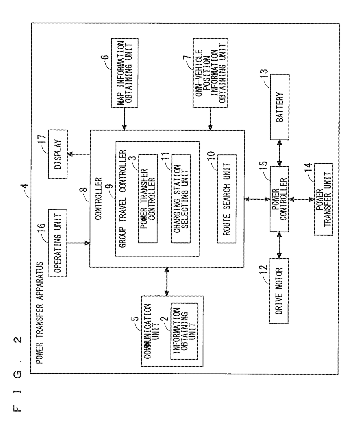
[0098]Embodiment 1 describes that the vehicles that travel in a group each include the group travel controller 9 in FIG. 2 and that the group travel controller 9 in each of the vehicles reselects a charging station. Embodiment 2 of the present invention will describe a case where a representative one of the vehicles that travel in a group performs processes on traveling in the group. Here, the vehicle that performs the processes on traveling in a group is the own vehicle, and the vehicles other than the own vehicle are the other vehicles. Since the power transfer apparatus included in each of the own vehicle and the other vehicles is identical to the power transfer apparatus 4 according to Embodiment 1, the description thereof will be omitted.

[0099]Next, operations of the own vehicle including the power transfer apparatus 4 will be described.

[0100]FIG. 14 is a flowchart illustrating an example of the operations performed by the power transfer apparatus 4 according to Embodiment 2.

[0...


PUM


Abstract

The present invention relates to a power transfer system and a power transfer method for efficiently transferring power between vehicles that travel in a group. The power transfer system according to the present invention is a power transfer system in a vehicle that can travel on power, the system including: an information obtaining unit that obtains possible driving distance information indicating a possible driving distance of each of vehicles that travel to a same destination; and a power transfer controller that controls, based on the possible driving distance information obtained by the information obtaining unit, transfer of power between a power-surplus vehicle with extra power and a power-shortage vehicle lacking in power so that the vehicles can reach a same charging station, the power-surplus vehicle and the power-shortage vehicle being included in the vehicles.

Description

TECHNICAL FIELD[0001]The present invention relates to a power transfer system and a power transfer method for transferring power between vehicles that travel to the same destination.BACKGROUND ART[0002]Conventionally, there have been techniques for supplying, among electric vehicles (EV) that travel in a platoon, power from a surplus-power vehicle with extra power to a power-shortage vehicle lacking in power. Here, the traveling in a platoon means that vehicles whose destinations are the same or different travel together along a common route. Vehicles may join or leave the platoon during their travel. Furthermore, the surplus-power vehicle with extra power means a vehicle having additional power other than the power necessary to travel up to a predetermined point, whereas the power-shortage vehicle lacking in power means a vehicle that does not have power necessary to travel up to a predetermined point.[0003]Examples of the techniques include a disclosed technique for supplying powe...

Claims


Application Information

Patent Timeline
Patent Type & Authority Applications(United States)
IPC IPC(8): G01C21/34B60L11/18
CPCG01C21/3469B60L11/1846B60L11/1824B60L11/1861G01C21/26G08G1/096716G08G1/096741G08G1/096791H04W84/005G01C21/3438B60L2240/62B60L2250/16B60L2260/52Y02T90/16Y02T10/7072B60L53/60B60L50/60Y02T10/70Y02T10/72Y02T90/12H04W4/02Y02D30/70H04W4/46H04W4/024Y02T90/14
Inventor YOSHIMURA, KEITOSHIMOTANI, MITSUO
Owner MITSUBISHI ELECTRIC CORP
Why Eureka
Try Eureka