Coil Topologies for Wireless Power Transfer

a topology and wireless technology, applied in the direction of exchanging data chargers, inductances, transportation and packaging, etc., can solve the problem of high inefficiency in the power transfer of the transmitter coil to the receive coil, and achieve the effect of efficient power transfer to the receiver

Inactive Publication Date: 2018-10-04
INTEGRATED DEVICE TECH INC
View PDF9 Cites 18 Cited by
  • Summary
  • Abstract
  • Description
  • Claims
  • Application Information

AI Technical Summary

Benefits of technology

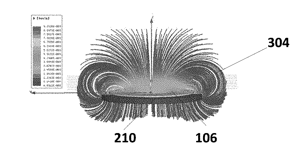
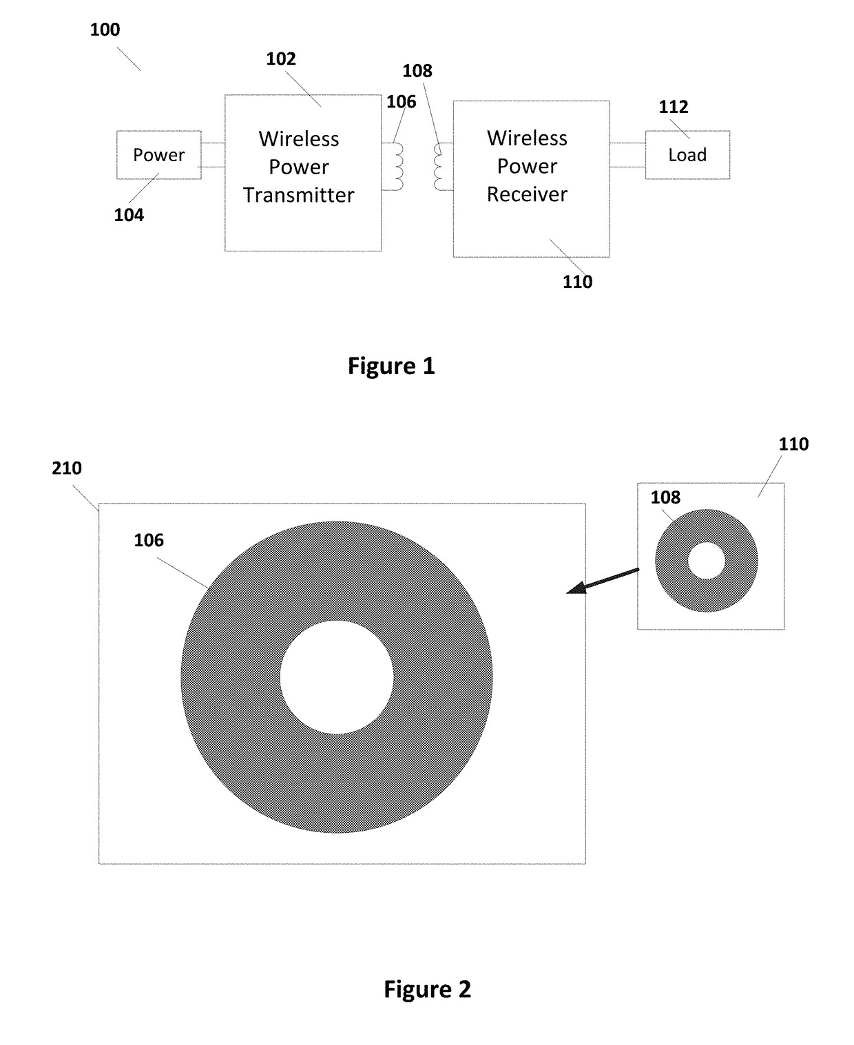
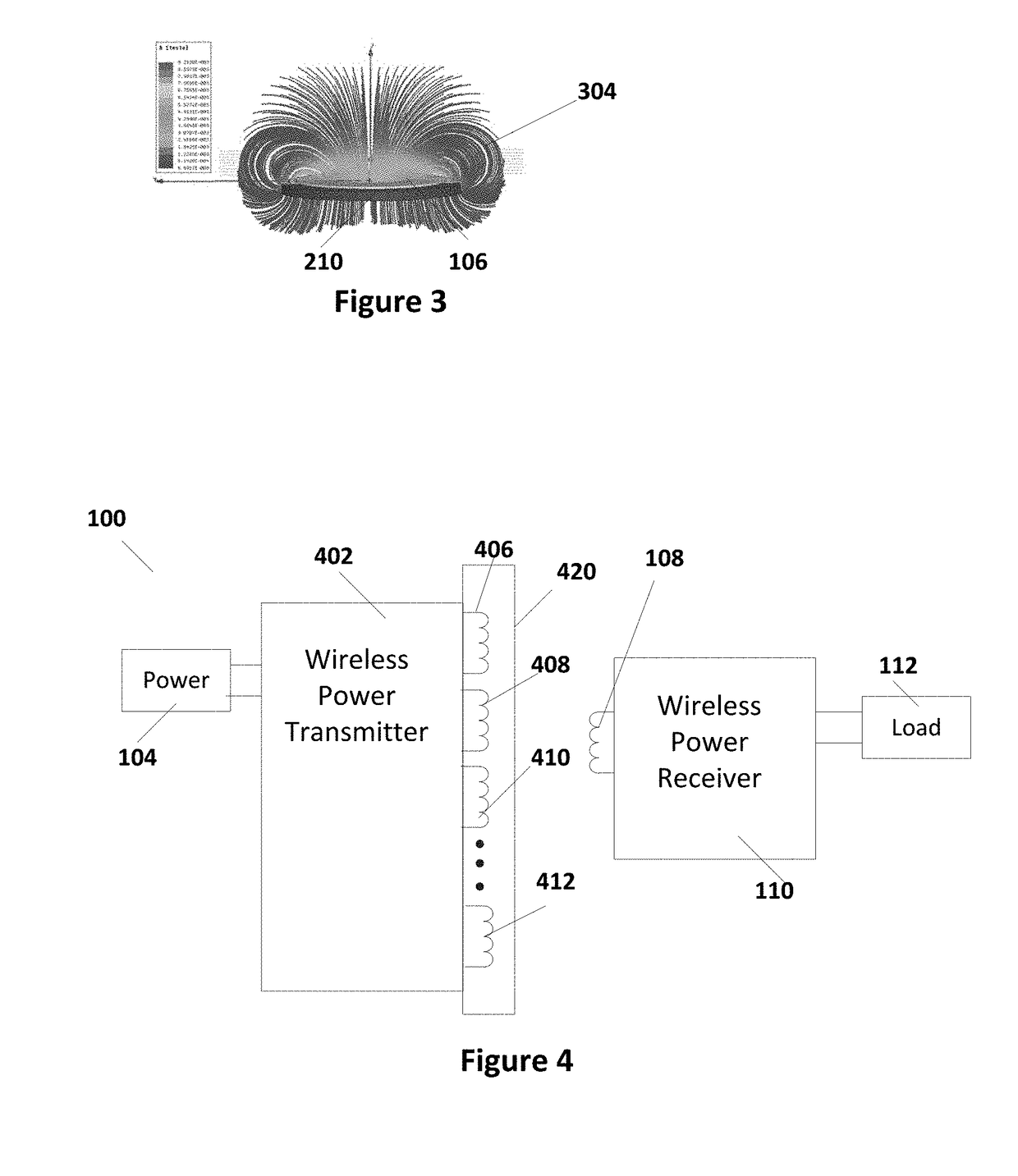
[0006]In accordance with some embodiments of the present invention, a wireless power transmitter is presented. The wireless power transmitter includes a plurality of coils, each of the plurality of coils arranged to cover an area within transmit area; and a transmitter circuit coupled to energize each of the plurality of coils, the transmitter circuit energizing one or more of the plurality of coils to efficiently transfer power to a receiver.

Problems solved by technology

However, in many cases the transfer of power from the transmitter coil to the receive coil can be highly inefficient, especially due to poor placement of the receiver coil relative to the transmit coil.

Method used


Image

  • Coil Topologies for Wireless Power Transfer
  • Coil Topologies for Wireless Power Transfer
  • Coil Topologies for Wireless Power Transfer

Examples


Embodiment Construction

[0016]In the following description, specific details are set forth describing some embodiments of the present invention. It will be apparent, however, to one skilled in the art that some embodiments may be practiced without some or all of these specific details. The specific embodiments disclosed herein are meant to be illustrative but not limiting. One skilled in the art may realize other elements that, although not specifically described here, are within the scope and the spirit of this disclosure.

[0017]This description and the accompanying drawings that illustrate inventive aspects and embodiments should not be taken as limiting—the claims define the protected invention. Various changes may be made without departing from the spirit and scope of this description and the claims. In some instances, well-known structures and techniques have not been shown or described in detail in order not to obscure the invention.

[0018]Elements and their associated aspects that are described in det...


PUM


Abstract

A wireless power transmitter is presented. The wireless power transmitter includes a plurality of coils, each of the plurality of coils arranged to cover an area within transmit area; and a transmitter circuit coupled to energize each of the plurality of coils, the transmitter circuit energizing one or more of the plurality of coils to efficiently transfer power to a receiver.

Description

RELATED CASES[0001]This disclosure claims priority to U.S. Provisional Application 62 / 481,026, filed on Apr. 3, 2017, which is herein incorporated by reference in its entirety.TECHNICAL FIELD[0002]Embodiments of the present invention are related to wireless power systems and, specifically, to coil topologies used in antennas of wireless power transmitters.DISCUSSION OF RELATED ART[0003]With the proliferation of wireless devices, wireless power has also become very popular. Charging stations, which do not require the user to carry a bundle of cables, are becoming available in a number of places. Furthermore, portable devices that allow for wireless charging are becoming more common. Wireless charging can be a convenient and fast method of charging mobile devices, as well as electric vehicles or other such devices.[0004]Power efficiency is a consideration in wireless transfer. A wireless transmitter can be powered by any power source, for example a standard A / C outlet, separate batter...

Claims


Application Information

Patent Timeline
Patent Type & Authority Applications(United States)
IPC IPC(8): H02J50/90H02J7/02H02J50/80
CPCH02J50/90H02J7/025H02J50/80H02J50/12H01F38/14H04B5/0037H02J50/10H01F27/38H04B5/0081H02J7/00034H02J50/402
Inventor WILSON, DAVIDMEHAS, GUSTAVO
Owner INTEGRATED DEVICE TECH INC
Why Eureka
Try Eureka