
Device for holding fish

a technology for fish and a holder, which is applied in the field of fish holder devices, can solve the problems of fish's mouth often times slipping out of the grip or puncturing, cumbersome use of products, and unreliable reliability,

Inactive Publication Date: 2008-11-06
BARFIELD TROY
View PDF13 Cites 57 Cited by
  • Summary
  • Abstract
  • Description
  • Claims
  • Application Information

AI Technical Summary

Benefits of technology

The invention relates to a device called a contact plate which can be attached to a tool by way of a rivet joint. This allows the contact plate to move freely without being permanently fixed to the tool. The technical effect of this design is improved flexibility for the user when making connections between tools, allowing them to work more efficiently and effectively.

Problems solved by technology

The technical problem addressed in this patent is how to safely and efficiently remove a hook from a fish's mouth without causing harm or discomfort to the fish. Current methods require two hands and cause stress for the fish, making them less likely to cooperate during removal. A new fish holding device is needed that can securely keep the fish in place while minimizing injury and damages to their mouth.

Method used


Image

  • Device for holding fish
  • Device for holding fish
  • Device for holding fish

Examples


Embodiment Construction

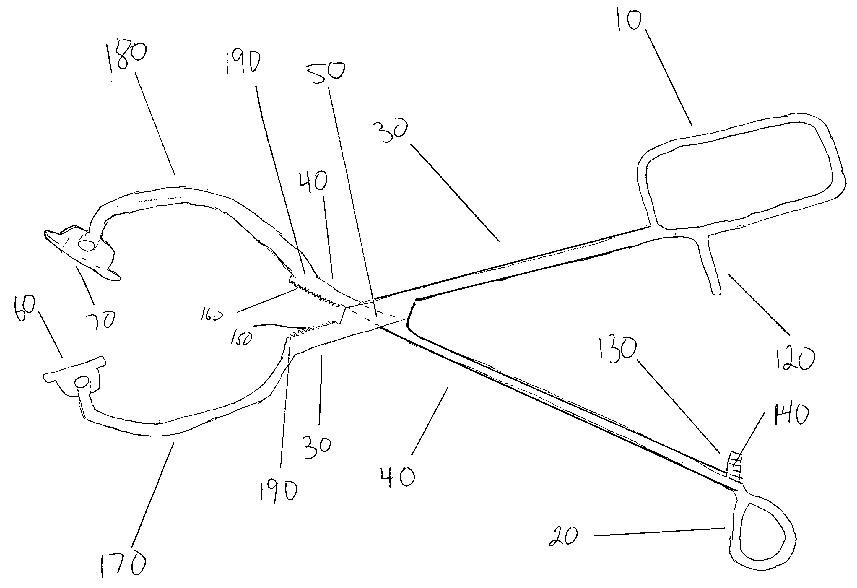
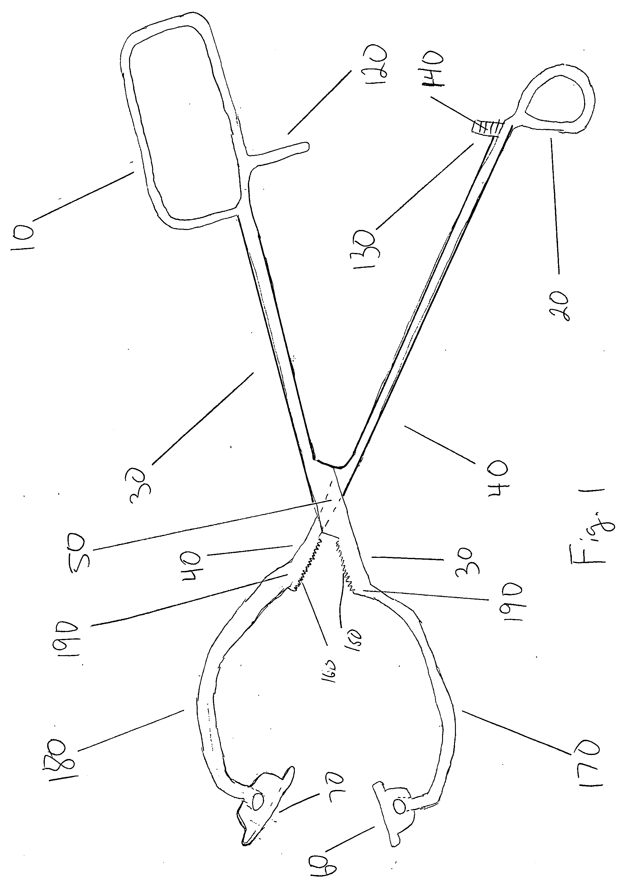
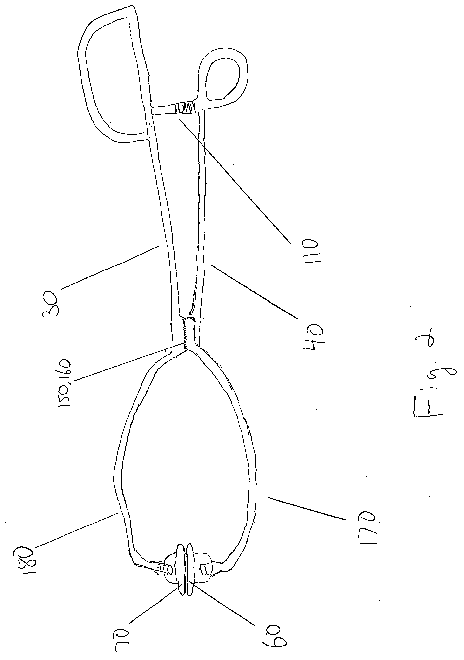
[0019]The present invention is a device for holding fish as set forth more particularly in the figures accompanying this application wherein like numerals refer to like elements across the various figures. The device of the present invention includes opposing first and second handles (10 and 20, respectively). A first arm and second arm (30 and 40, respectively) connect to the first (10) and second (20) handles. The first (30) and second (40) arms are connected to one another in an overlapping scissor-like fashion at a connection point (50). In one embodiment of the invention, first and second contact plates (60 and 70, respectively) are attached to the first (30) and second (40) arms at the end of the first and second arms opposite the first (10) and second (20) handles.

[0020]In one embodiment of the invention as set forth in FIG. 10, the first (60) and second (70) contact plates are connected to the first (30) and second (40) arms in a static manner such that the contact plates do...


PUM


Abstract

The present invention is a device for holding fish, said device comprising first and second handles attached to first and second arms. The first and second arms are connected in scissor-like fashion. The first and second arms are connected to first and second contact plates. The first and second contact plates pinch the inside and outside of a fish's mouth when the device is in the closed position, thereby allowing a fish to lifted out of the water or off the ground. The present invention may also comprise first and second tongs attached to first and second arms. In this embodiment, the first and second tongs are shaped substantially like semi-ovals and are attached to the first and second contact plates.

Description


Claims


Application Information

Patent Timeline
Owner BARFIELD TROY
Features
  • Generate Ideas
  • Intellectual Property
  • Life Sciences
  • Materials
  • Tech Scout
  • Unparalleled Data Quality
  • Higher Quality Content
  • 60% Fewer Hallucinations
Learn More