Shielded connector structure

a shielding and connector technology, applied in the direction of coupling device connection, coupling protective earth/shielding arrangement, electrical equipment, etc., can solve the problems of affecting the free flow of return current and the inability to appropriately discharge electrical noise, and achieve the effect of effective release of noise and satisfactory shielding property

Active Publication Date: 2009-01-22
YAZAKI CORP
View PDF12 Cites 25 Cited by
  • Summary
  • Abstract
  • Description
  • Claims
  • Application Information

AI Technical Summary

Benefits of technology

[0010]The object of the present invention is to resolve this problem. Specifically, the object of this invention is to provide a shielded connector structure that effectively releases noise by shortening a path for the flow of a return current, and that thus exhibits a satisfactory shielding property.

Problems solved by technology

Since high voltages are normally supplied for this type of motor, there are problems that external leakage of electrical noise originating at a metal terminal element provided on a power supply terminal occurs, or that such noise flows from one such terminal metal element to another.
Accordingly, because of electric resistance along the path, the free flow of the return current is impeded and the electrical noise can not be appropriately discharged.

Method used


Image

  • Shielded connector structure
  • Shielded connector structure
  • Shielded connector structure

Examples


first embodiment

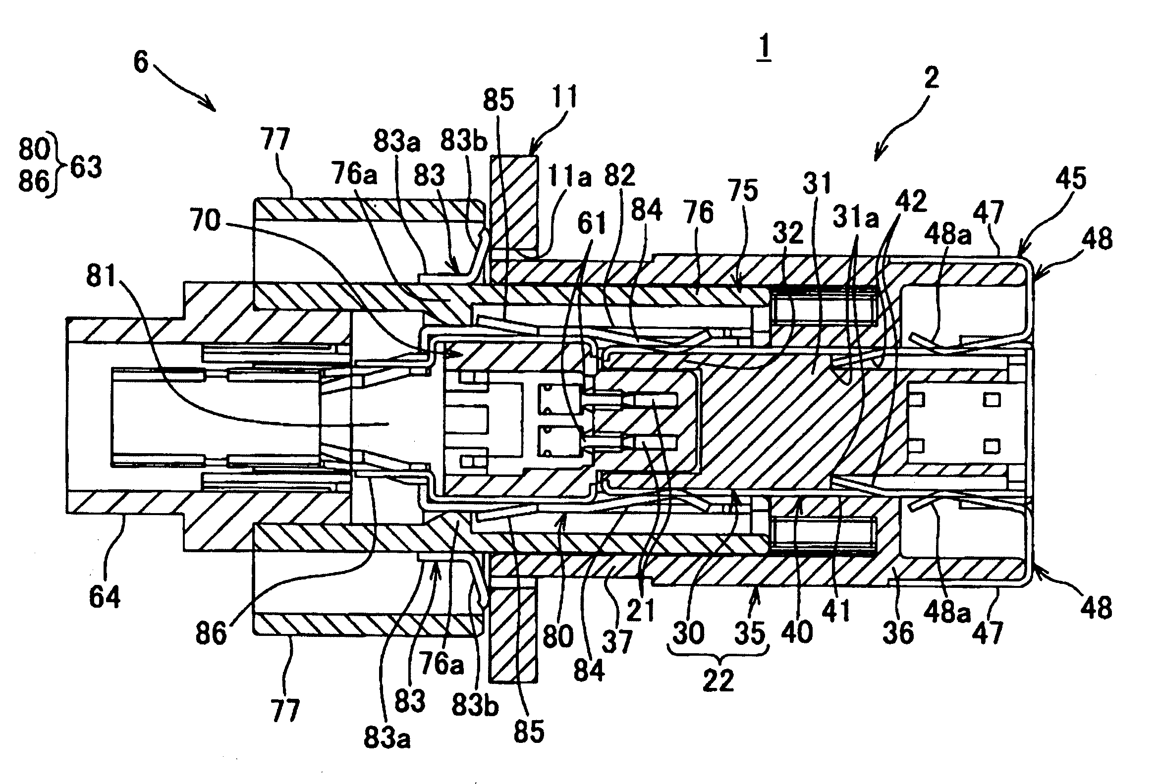
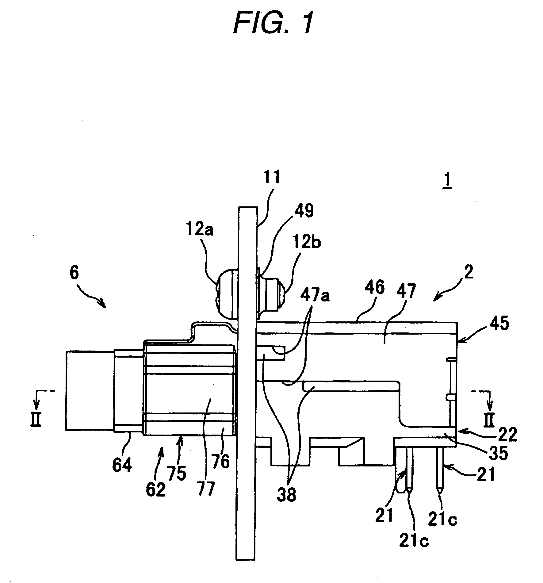
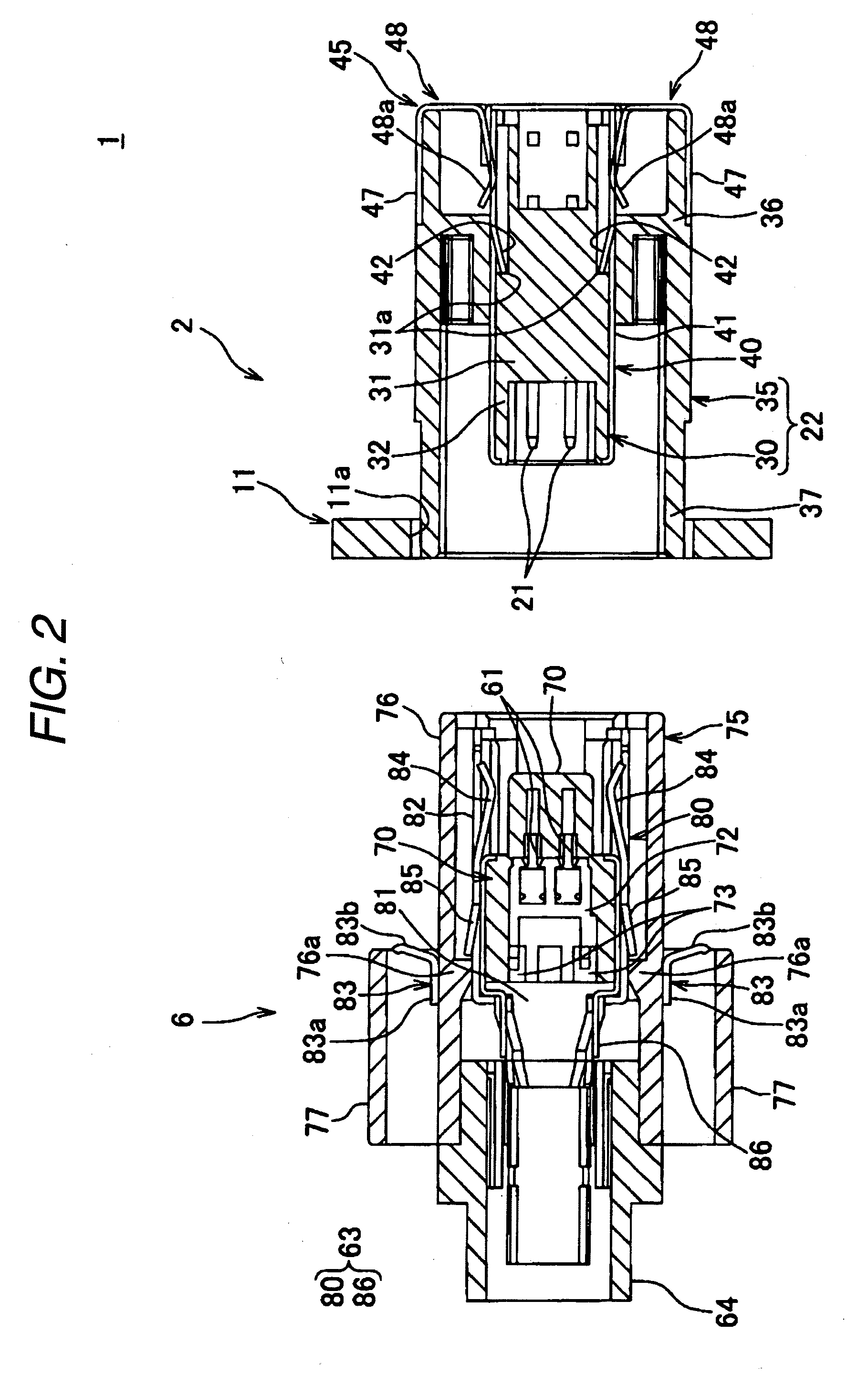
[0058]A shielded connector structure 1 according to a first embodiment of the present invention will now be described while referring to FIGS. 1 to 7. As shown, for example, in FIG. 1, the shielded connector structure 1 of the first embodiment includes: a pair of connectors 2 and 6 that engage each other and that include shield shells 23 (FIG. 7) and 63 (FIG. 5), respectively; and a conductive connector mounting portion 11 which contacts the shield shell of at least one of the connectors, e.g., the shield shell 23 of the first connector 2, to ground the shield shell 23. When the connectors 2 and 6 are engaged, the shield shells 23 and 63 are shield-connected.

[0059]The term, “shield-connected” is used to describe an operating state existing when the shield shells 23 and 63 are connected and circumferentially enclose metal terminal elements 21 and 61 which will be described later. When the shield shells 23 and 63 are shield-connected, electrical noise that leaks externally or enters t...

second embodiment

[0105]A shielded connector structure 1 according to a second embodiment of the present invention will now be described while referring to FIGS. 8 to 14. The same reference numerals used for the first embodiment are provided on identical or corresponding components, and no further explanation for them will be given.

[0106]As shown in FIG. 8, the shield connector structure 1 for the second embodiment includes: a pair of connectors 2 and 6, which engage each other and which include shield shells 23 and 63 respectively; and a conductive connector mounting portion 11, which contacts and grounds the shield shell 23. When the connectors 2 and 6 are engaged, the shield shells 23 and 63 are shied-connected.

[0107]In this embodiment, unlike in the first embodiment, connecting portions 83 are not formed on a lower shield shell 80 of the second connector 6, and instead, second connecting portions 91 are formed on an outer shield shell 45 of the first connector 2.

[0108]As shown in FIGS. 9 and 13, ...


PUM


Abstract

A shielded connector structure includes a first connector and a second connector, each having a metal terminal element, an insulating connector housing that has a terminal container for accommodating the metal terminal elements, and a conductive shield shell which covers the terminal container of the connector housing. The shielded connector structure further includes a conductive connector mounting portion which contacts the shield shell of at least one of the first and second connectors to ground the shield shell; and a connecting portion which is provided on each of the shield shells of the first and second connectors, and is coupled to the connector mounting portion when the first and second connectors are engaged to shield-connect the shield shells each other.

Description

BACKGROUND OF THE INVENTION[0001]1. Technical Field[0002]The present invention relates to a shielded connector structure which includes a pair of connectors each having a conductive shield shell covering a connector housing which accommodates a metal terminal element, and a conductive connector mounting portion, and in which a shield shell that is grounded at the connector mounting portion to discharge a noise.[0003]2. Background Art[0004]Various electronic apparatuses are mounted in a mobile vehicular body configured as an automobile. Therefore, wire harnesses are prepared and installed in order to supply electric power and signals to the electronic apparatuses on the automobile. These wire harnesses includes multiple electric wires and connectors attached to the wires.[0005]A three-phase electric motor may be employed as a driving motor in the above-mentioned automobile such as an electric car, a hybrid car and a fuel-cell vehicle. Since high voltages are normally supplied for thi...

Claims


Application Information

Patent Timeline
Patent Type & Authority Applications(United States)
IPC IPC(8): H01R13/648H01R13/658
CPCH01R13/748H01R12/712H01R13/6583
Inventor KAMEYAMA, ISAONOJIMA, MOTOO
Owner YAZAKI CORP
Why Eureka
Try Eureka