

Video conference system
- Summary
- Abstract
- Description
- Claims
- Application Information
AI Technical Summary
Benefits of technology
Problems solved by technology
Method used
Image

Examples
Embodiment Construction
[0021]An example 1 of the video conference according to the present invention will be explained by referring to FIGS. 1-5.
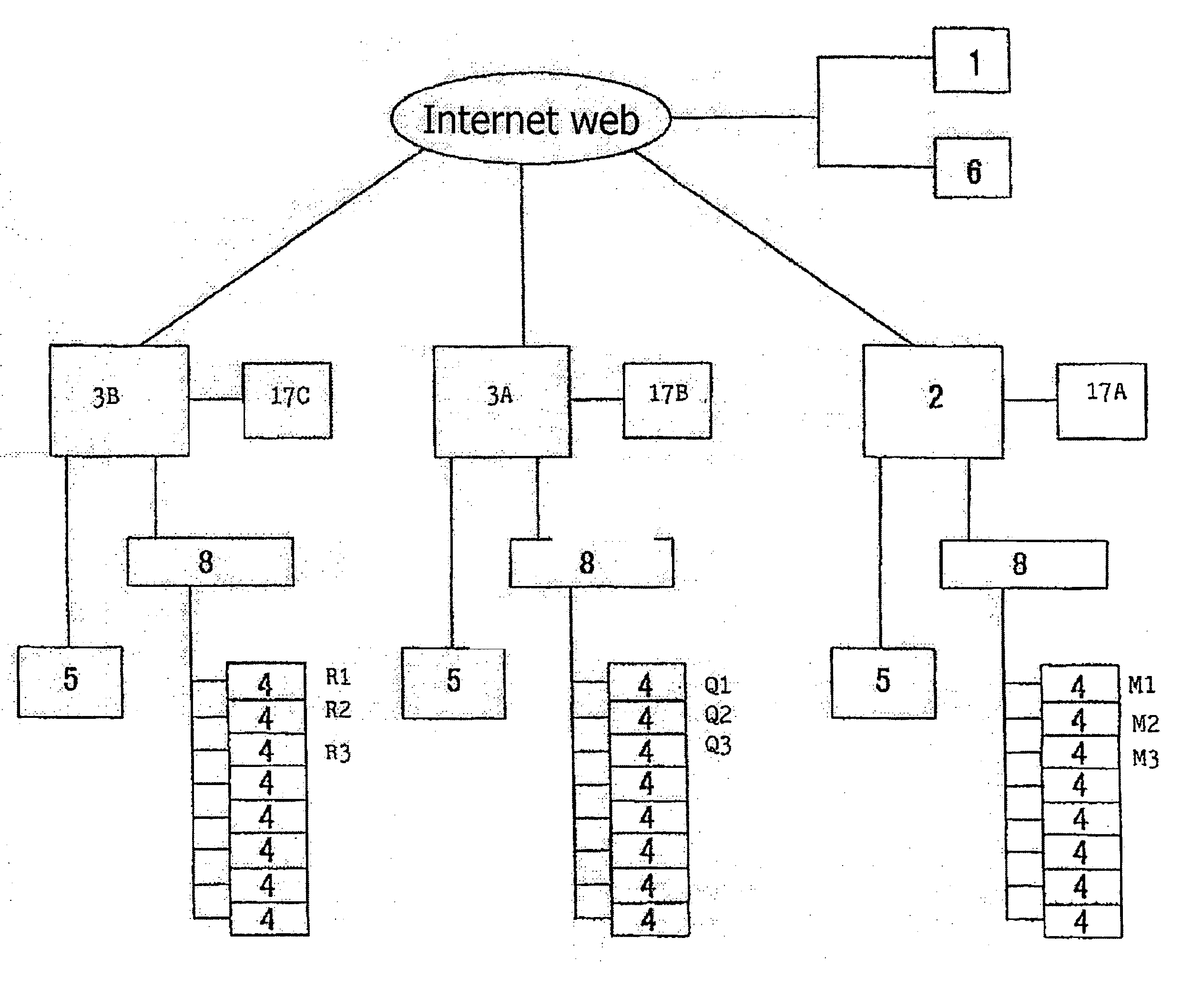
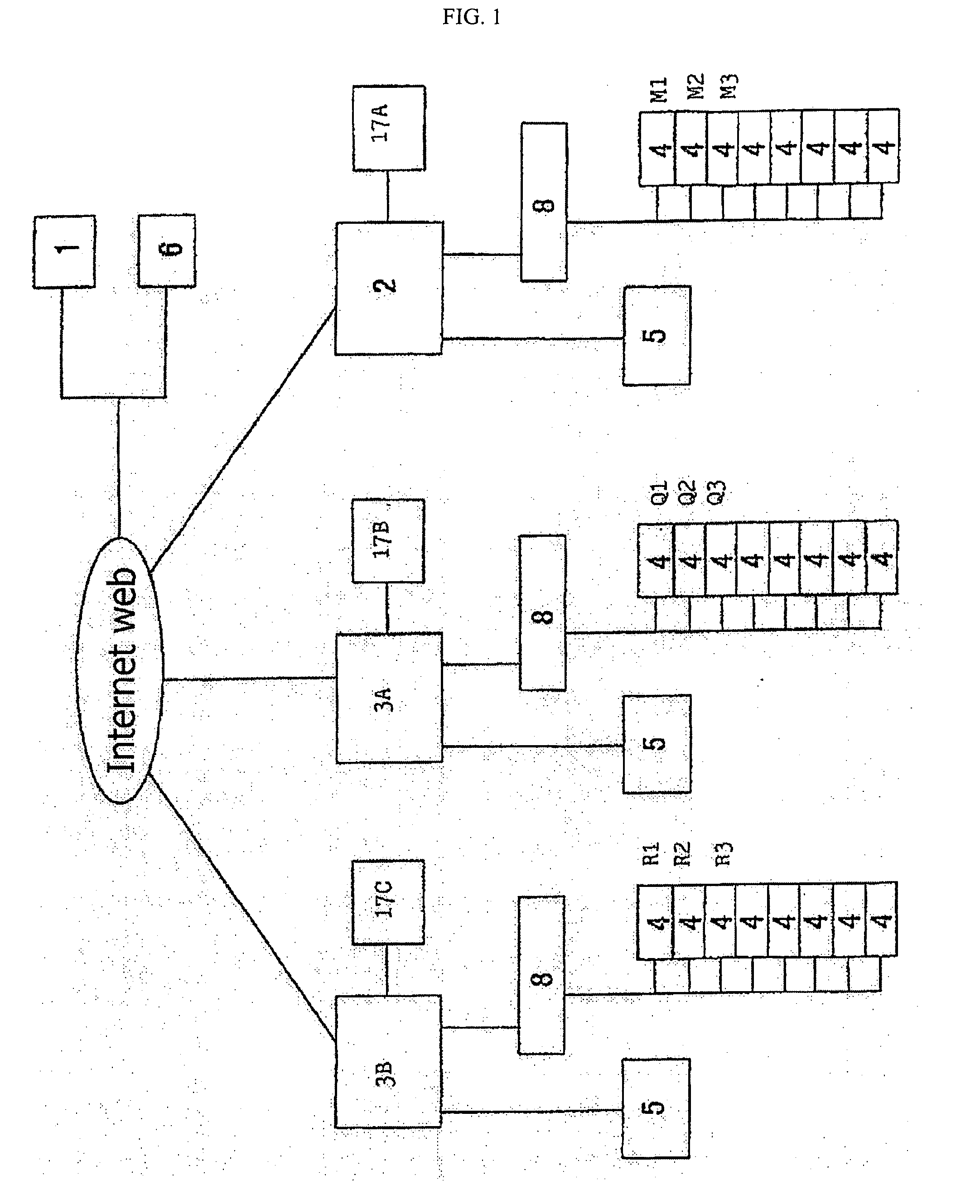
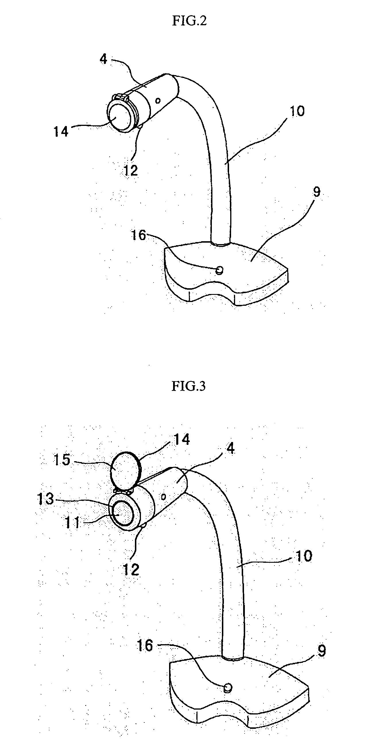
[0022]The videoconference system of the present invention, as shown in FIG. 1, comprises a conference server 1 placed at a head office; one head office controller 2 placed at the head office and connected via Internet to the conference server 1; and a plurality of local controllers 3A and 3B which are placed at each local office and connected to the conference server 1 via the Internet, respectively. Hereinafter, in order to make an explanation easier, an example of installing two local controllers will be explained as shown in FIG. 1. Camera-equipped microphones 4 and a magnified monitor 5 are connected to each of head office controller 2 and local controllers 3A and 3B.
[0023]The conference server 1 includes a database function to maintain system information, conference reservation information, and information regarding the head office and each local office and ...
PUM
 Abstract
Description
Claims
Application Information