
Control apparatus of automatic transmission

Active Publication Date: 2007-06-28
JATCO LTD +1
View PDF6 Cites 16 Cited by
  • Summary
  • Abstract
  • Description
  • Claims
  • Application Information

AI Technical Summary

Benefits of technology

[0007]In JP62-46055, however, the speed change is carried out from a current speed to a target speed by mere plural sequential shifts. In this case, the greater the difference between the current speed and the target speed (desired or final speed), the more the number of shift increases. Thus, this causes the occurrence of shift shock and the increase of time required to reach the target speed, and drivability therefore deteriorates. Further, in this JP62-46055, the speed change is made in a short time by usage of higher hydraulic pressure than normal hydraulic pressure in hydraulic pressure control. However, assuming that the normal hydraulic pressure is set to such an optimum pressure that the shift shock does not occur, in the case where the hydraulic pressure is increased, there arises a problem that the shift shock deteriorates or this aggravates the shift shock.
[0009]It is therefore an object of the present invention to provide an automatic transmission which completes the shift speedily at the sequential shift while minimizing the increase of the data even the multispeed automatic transmission, and suppresses the deterioration in the drivability and the occurrence of shift shock.

Problems solved by technology

Thus, this causes the occurrence of shift shock and the increase of time required to reach the target speed, and drivability therefore deteriorates.
However, assuming that the normal hydraulic pressure is set to such an optimum pressure that the shift shock does not occur, in the case where the hydraulic pressure is increased, there arises a problem that the shift shock deteriorates or this aggravates the shift shock.
Nevertheless, a proper way of such speed change (or speed change pattern or shift pattern) has not been taken account of in detail.
Because of this, in the above particular shift pattern, in the case of the shift from the primary shift to the secondary shift, if speed change control is executed without considering the engagement state of the frictional element, there is a possibility that a considerable shift shock will occur.

Method used


Image

  • Control apparatus of automatic transmission
  • Control apparatus of automatic transmission
  • Control apparatus of automatic transmission

Examples


Embodiment Construction

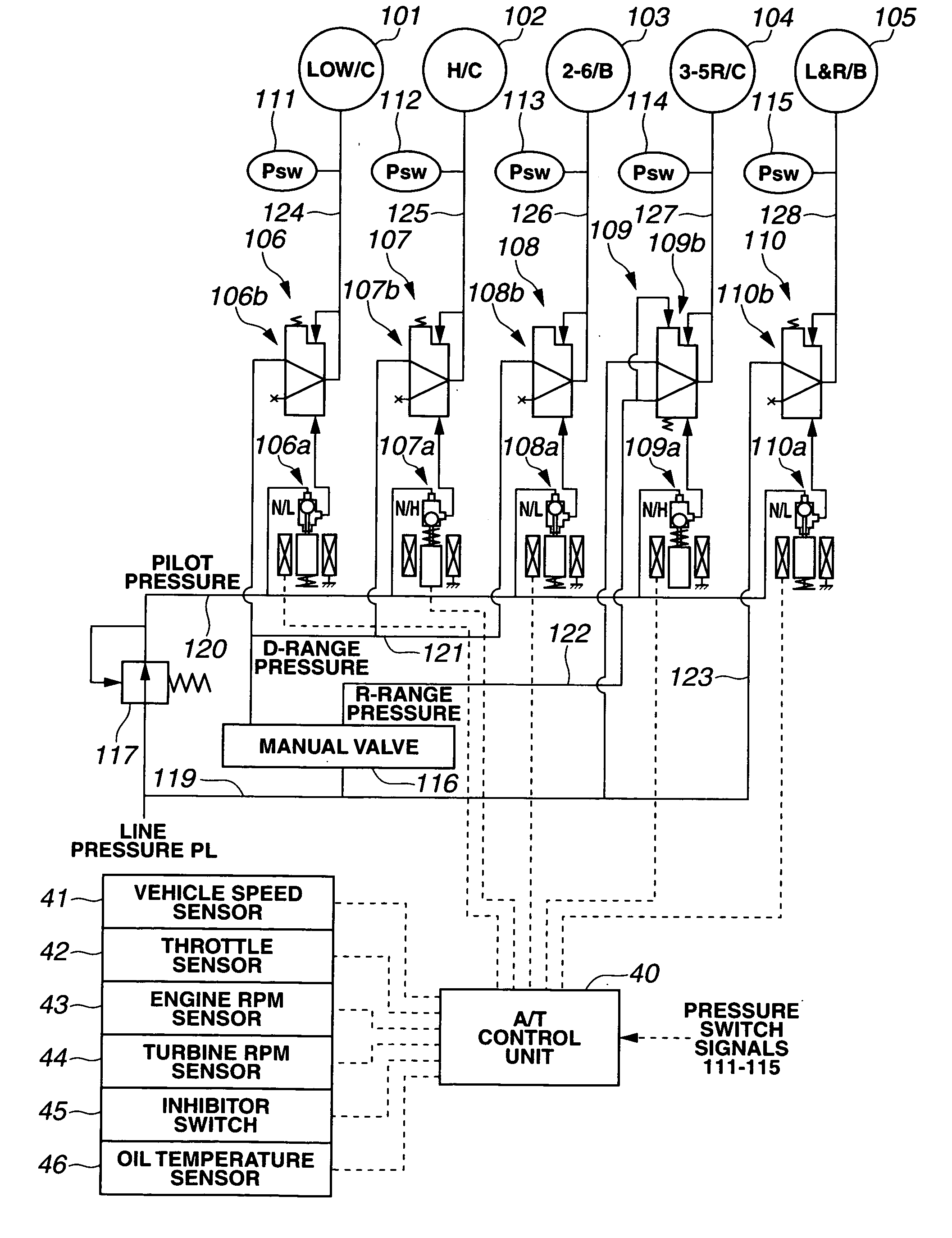
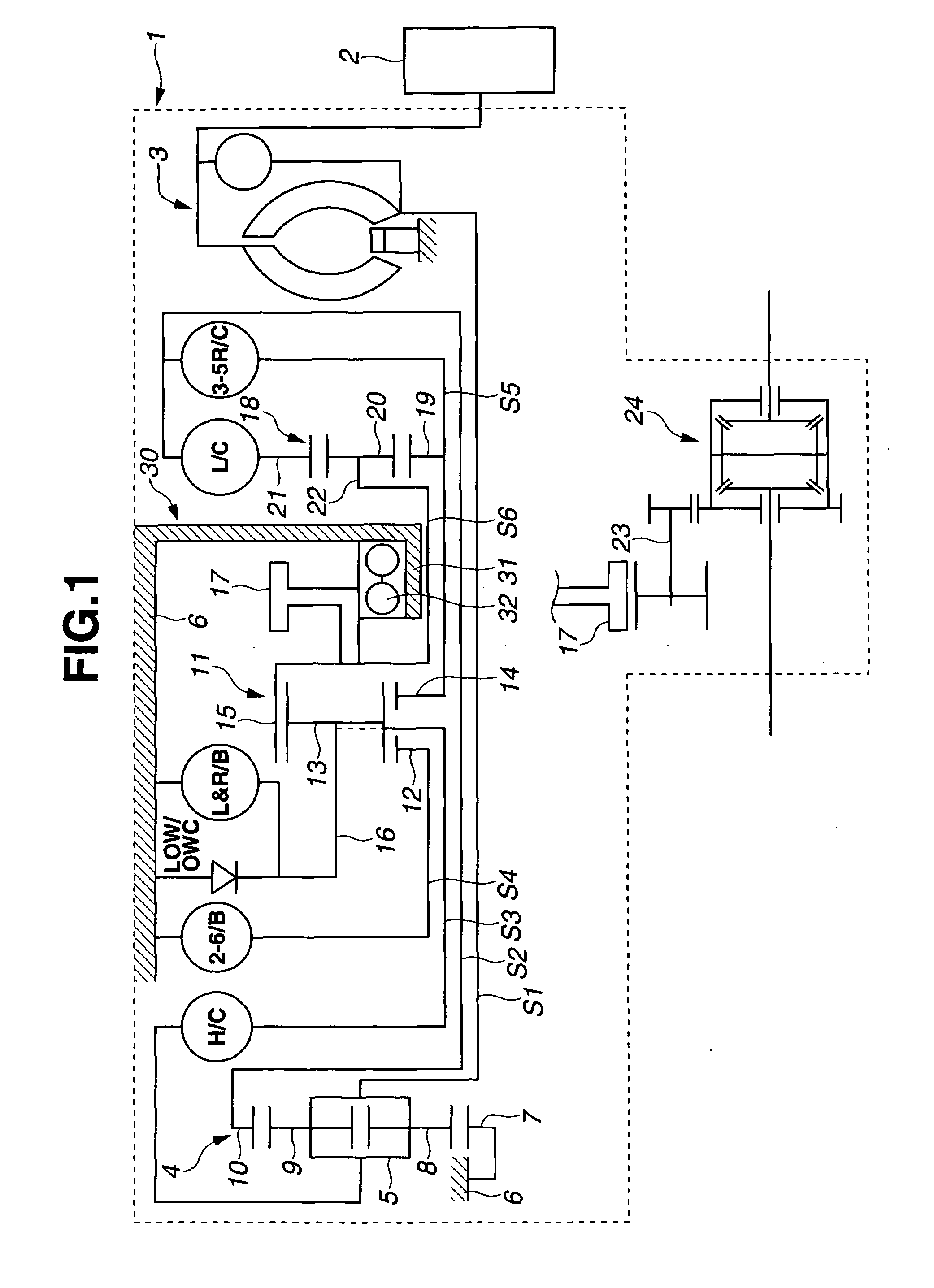
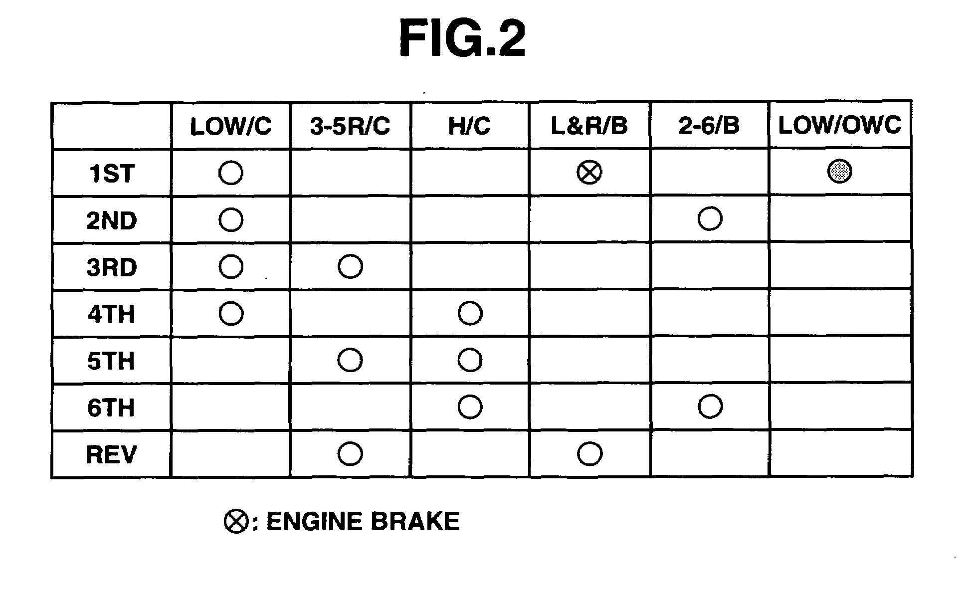
[0029]A control apparatus of an automatic transmission of the present invention will be explained below with reference to the drawings.

1. Configuration of The Automatic Transmission

[0030]FIG. 1 is a schematic view of a six forward speed and one reverse speed automatic transmission 1 to which the present invention is applied. As seen in FIG. 1, an engine power from an engine 2 is input to a torque converter 3, and further input to a carrier 5 of a double pinion type planetary gear unit (a first planetary gear unit) 4 through a first rotation shaft S1.

[0031]Double pinion type planetary gear unit 4 has a sun gear 7 secured to a transmission case 6, inside pinion gears 8 meshed with sun gear 7, outside pinion gears 9 meshed with inside pinion gears 8, a ring gear 10 that is meshed with outside pinion gears 9 and is coaxially aligned with sun gear 7, and the above-mentioned carrier 5 that rotatably supports inside and outside pinion gears 8 and 9.

[0032]Ring gear 10 is connected to a seco...


PUM


Abstract

A control apparatus of an automatic transmission includes first, second and third frictional elements, first and second shift control sections issuing a hydraulic pressure command to the first, second and third frictional elements for engagement and release thereof at primary and secondary shifts, a judging section judging a shift from a first speed stage to a third speed stage, and a third shift control section initiating the primary shift when the shift is judged, and initiating the secondary shift before an end of the primary shift while executing the primary shift when a gear ratio reaches a first predetermined gear ratio. the third shift control section compares two pressure command values of the first frictional element, respectively issued by the first and second shift control sections for the primary and secondary shifts, and selects a greater pressure command value, and outputs it to the first frictional element.

Description

BACKGROUND OF THE INVENTION[0001]The present invention relates to a control apparatus of an automatic transmission mounted on a vehicle, and more particularly to a control apparatus for a multispeed automatic transmission that has five or over five speeds.[0002]In recent years, the number of speeds of automatic transmissions has increased, and also the number of frictional elements such as clutches and brakes has increased with the increase of the number of speeds. Further, a spacing or interval between speed change lines (or shift lines) in a shift map becomes much denser with such increase of the number of speeds. For this reason, speed change easily takes place even according to a small change of operation condition of the vehicle (for instance, a change of throttle opening). Thus, when the interval of shift lines in the shift map becomes denser in this way, so-called two skip shift (for example, shift from 6th speed to 3rd speed) or three skip shift (for example, shift from 6th ...

Claims


Application Information

Patent Timeline
IPC IPC(8): B60W10/00
CPCF16H61/0437F16H61/061F16H61/686F16H2061/0444Y10T477/638F16H2061/0455F16H2200/0052F16H2306/24F16H2061/0451F16H61/04
Inventor INUTA, YUKIYOSHI
Owner JATCO LTD
Learn More