Ultrasonic imaging apparatus and ultrasonic imaging method

Inactive Publication Date: 2009-01-29
GE MEDICAL SYST GLOBAL TECH CO LLC
View PDF20 Cites 9 Cited by
  • Summary
  • Abstract
  • Description
  • Claims
  • Application Information

AI Technical Summary

Benefits of technology

[0037]In the invention of the seventeenth aspect, the infl

Problems solved by technology

According to the background art, however, the work of the operator is cumbersome and is not easy to concentrate on the acquisition of the opti

Method used


Image

  • Ultrasonic imaging apparatus and ultrasonic imaging method
  • Ultrasonic imaging apparatus and ultrasonic imaging method
  • Ultrasonic imaging apparatus and ultrasonic imaging method

Examples


embodiment 1

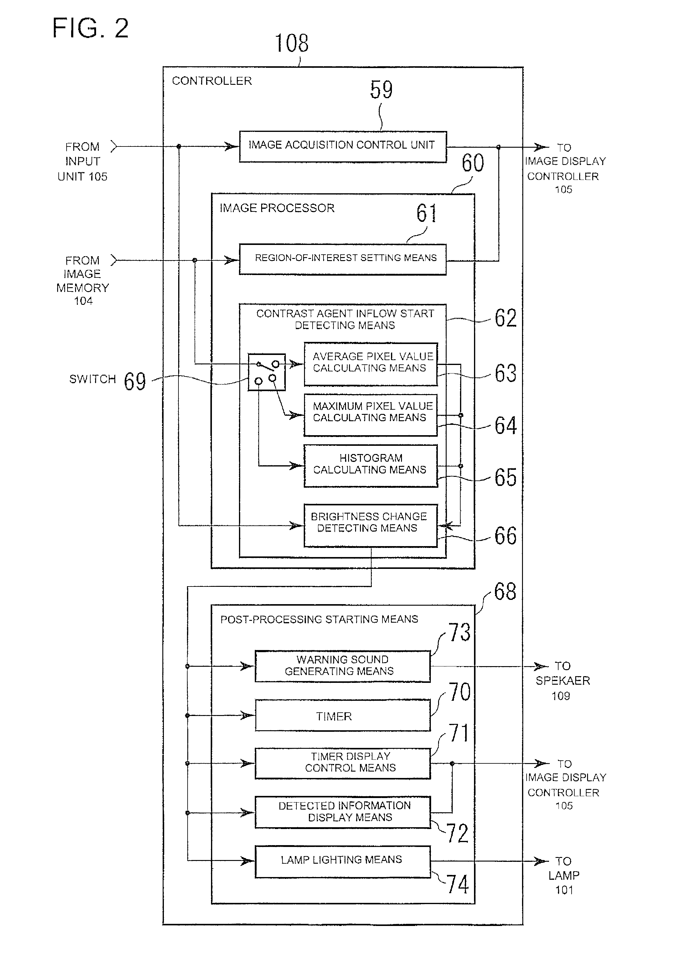
[0084]The detected information display means 72 displays detected information about the average pixel value, maximum pixel value, time intensity curve, histogram and the like in sync with the brightness change detection signal outputted from the brightness change detecting means 66. Incidentally, in the present embodiment 1, the detected information display means 72 displays an indicator indicative of the average pixel value on the display unit 106.

[0085]The operation of the controller 108 according to the embodiment 1 will next be explained using FIG. 3. FIG. 3 is a flowchart showing the operation of the controller 108. An operator first performs initial setting on the controller 108 (Step S301). Upon the initial setting, settings such as the selection of a B-mode, the startup of the contrast agent inflow start detecting means for automatically detecting the inflow of a contrast agent into the corresponding imaging region, a method for detection processing, the input of a threshold...

embodiment 2

[0118]Though the histograms for the imaging region have been determined by the histogram calculating means 65 in the present embodiment 2, it is also capable of setting a region of interest to the imaging region in like manner, determining histograms related to the region of interest and detecting a change in brightness.

[0119]Though the histograms for the imaging region have been determined by the histogram calculating means 65 in the present embodiment 2, it is also possible to cause the display unit 106 to display the histograms and visually determine the inflow of the contrast agent into the imaging region.


PUM


Abstract

An ultrasonic imaging apparatus includes: an image acquisition unit which acquires B-mode image information on an imaging region lying within a subject; a display unit which displays the B-mode image information thereon; a contrast agent inflow start detecting device which detects an inflow timing at which a contrast agent administered to the subject starts to flow in the imaging region, using the B-mode image information; and a post-processing starting device which starts up post-processing conducted after the contrast agent has started to flow in the imaging region, in sync with the inflow timing.

Description

CROSS REFERENCE TO RELATED APPLICATIONS[0001]This application claims the benefit of Japanese Patent Application No. 2007-193979 filed Jul. 26, 2007, herein incorporated by reference in its entirety.BACKGROUND OF THE INVENTION[0002]The subject matter disclosed herein relates to an ultrasonic imaging apparatus which displays a B-mode image of a subject to which a contrast agent is administered.[0003]It has recently been practiced to administer a contrast agent to a subject and image or photograph the administered contrast agent using a B-mode image of an ultrasonic imaging apparatus. The contrast agent comprises liquid containing a large quantity of bubbles. The contrast agent administered to the subject circulates within a body with time. Ultrasound produced from the ultrasonic imaging apparatus at this time is strongly reflected from the contrast agent and the contrast agent is plotted or drawn as a B-mode image high in signal intensity. A time change in the contrast agent that circ...

Claims


Application Information

Patent Timeline
IPC IPC(8): A61B8/14
CPCA61B8/06A61B8/13A61B8/461G01S7/52074A61B8/481G01S7/52063A61B8/469A61B8/463A61B8/00
Inventor FUJIWARA, CHIORIABE, YAYOIMIYAMA, KOJI
Owner GE MEDICAL SYST GLOBAL TECH CO LLC
Why Eureka
Try Eureka