
Bin

a technology for bins and bin covers, applied in the field of bins, can solve the problems of undesirable noise, undesirable noise, and bins with bin covers

Inactive Publication Date: 2009-03-19
FMC MFG
View PDF9 Cites 41 Cited by
  • Summary
  • Abstract
  • Description
  • Claims
  • Application Information

AI Technical Summary

Benefits of technology

[0066]a damper mechanism for creating friction between the stationary member and the moveable member when they are in motion relative to each other.
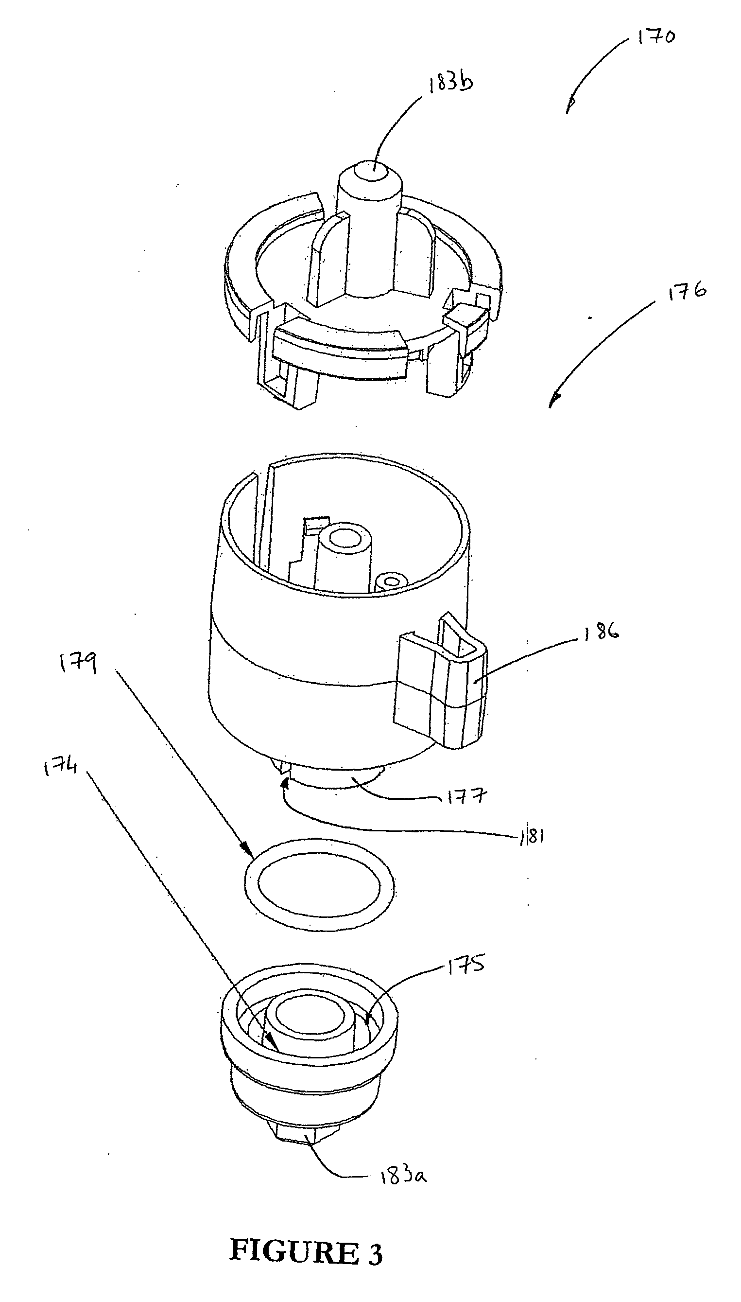
[0070]Preferably, one or both of the stationary member and the moveable member may have drag formations for creating hydraulic drag through fluid contained in the fluid compartment, thereby damping movement of the pivoting member relative to the stationary member.

Problems solved by technology

Such conventional pedal rubbish bins have a common disadvantage in that they are noisy, both when opening the bin lid and when the bin lid is allowed to close under its own weight.
When the bin lid of a conventional rubbish bin is opened by means of the foot pedal, the mechanical linkages of the lid opening mechanism can cause undesirable noise.
Also, upon the closure of the bin lid under its own weight, the noise of the bin lid hitting the rim of the bin can cause undesirable noise.
A conventional pedal bin also has a disadvantage in that it may be inconvenient to a user who wishes to keep the lid of the bin open, but can only do so by holding the pedal down.
This may not always be desirable.
Further, conventional pedal bins have a disadvantage in that the pedal needs to physically depressed in order to open the lid.
This may not always be possible, for instance when a user is otherwise incapacitated, or wearing shoes which make this inconvenient.
However, these existing bins with sensors have a disadvantage in that it may not be possible or safe to clean or wash these bins under running water, or by submerging them because of the presence of electrical motors, batteries and other electronic or electrical components.
Further, when a user is required to stand in front of the bins in order to activate the sensor, this may be disadvantageous if it is not convenient or possible for someone to move exactly to the front of the bin.
Another main disadvantage of conventionally known rubbish bins, is that odour is known to leak from rubbish bins to the ambient environment when the lid of the bin is open.
Similarly, germs and viruses may also be spread from such a bin, causing a health hazard.

Method used


Image

  • Bin
  • Bin
  • Bin

Examples


Embodiment Construction

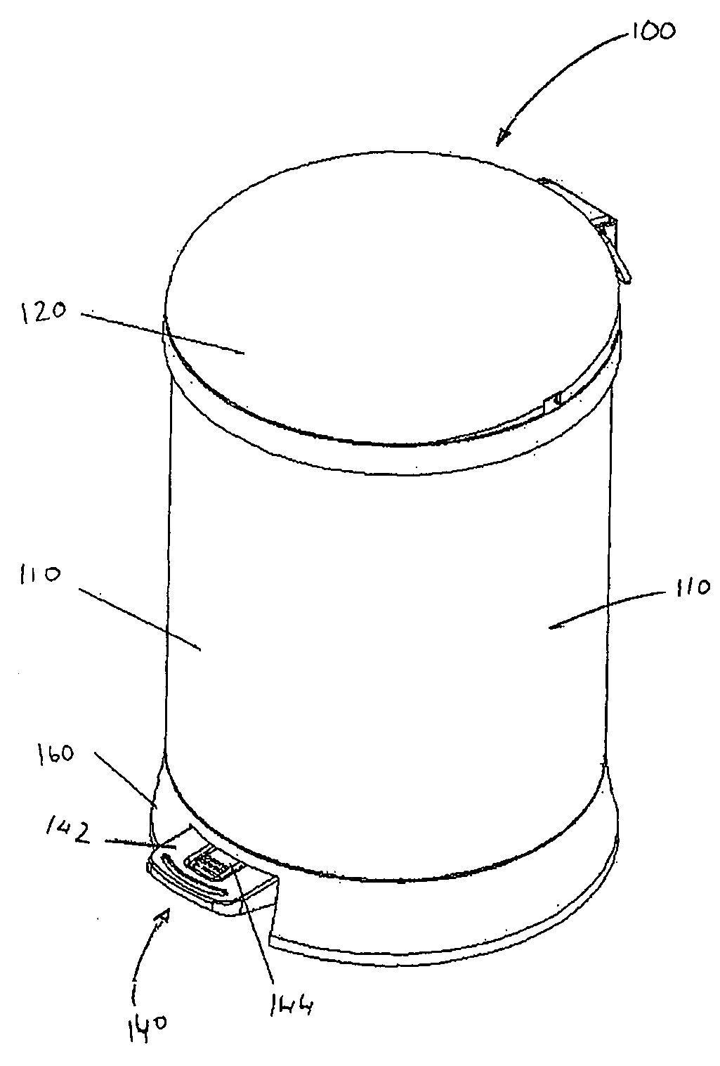
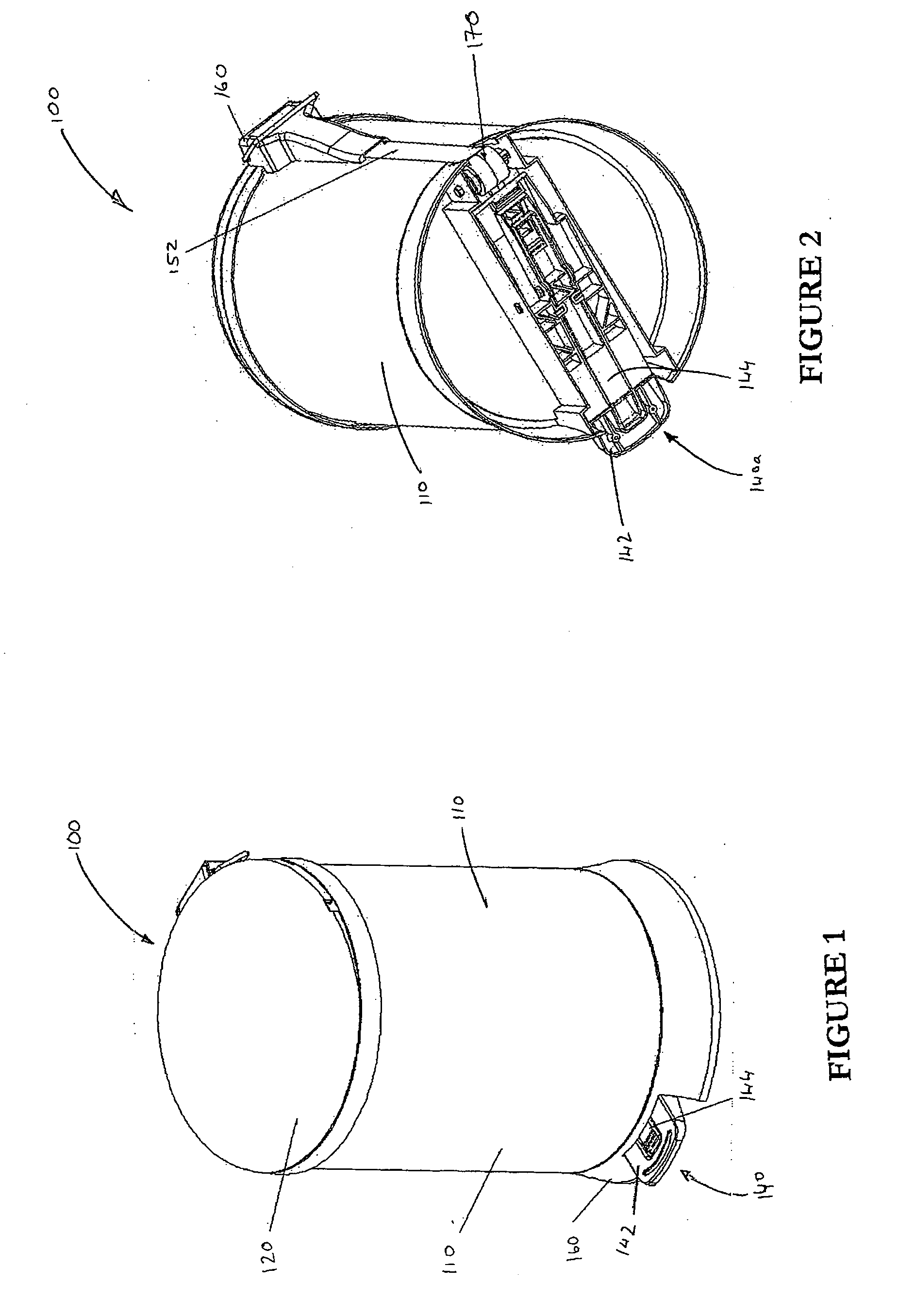
[0331]With reference to the accompanying figures, a bin according to a first aspect of the invention is generally indicated by the numeral 100.

[0332]In one embodiment according to the invention now described, there is provided a bin 100, suitable for the retention of rubbish. The bin 100 comprises a container 110, and a lid 120 which is pivotable about an axis 122 to move between an open position (as shown in FIGS. 8, 9, 19, and 20) in which items, such as domestic rubbish, are received into the container 110, and a closed position (as shown in FIGS. 1, 7, 10, 11, 12, 13, 16, 17, 18, 21 and 22) in which access to the container is sealed by the lid 120, preferably by an airtight seal to prevent smells escaping. The bin 100 further comprises a lid actuating device 130 for moving the lid 120 between the open position and closed positions.

[0333]The lid actuating device 130 includes an actuator mechanism 140, shown in this embodiment as a foot pedal mechanism 140a, actuatable by a user (...


PUM


Abstract

A bin, suitable for the retention of rubbish, said bin comprising a container, a lid which is moveable between an open position in which rubbish may be received into the container, and a closed position in which access to the container is at least partially restricted. A lid actuating device for moving the lid between the open position and closed positions. The lid actuating device including an actuator mechanism and a lever mechanism including at least one tensile member which can be tensioned by actuation of the actuator mechanism to cause movement of the lid towards the open position.

Description

FIELD OF THE INVENTION[0001]The present invention relates to a bin. More particularly, but not exclusively, it relates to a rubbish bin including a mechanism for opening and closing a top lid.BACKGROUND TO THE INVENTION[0002]Rubbish bins, such as those used domestically, are well known throughout the world. Many of those include a foot pedal mechanism, which, when operated by a user's foot, cause a lid on top of the rubbish bin to lift, thereby giving a user access to the bin. When the user's foot is removed from the pedal, the bin lid falls down under its own weight.[0003]Such bins typically use a foot driven lever mechanism which actuates a push rod. The push rod pushes the bin lid into an open position. Such conventional pedal rubbish bins have a common disadvantage in that they are noisy, both when opening the bin lid and when the bin lid is allowed to close under its own weight.[0004]When the bin lid of a conventional rubbish bin is opened by means of the foot pedal, the mechan...

Claims


Application Information

Patent Timeline
IPC IPC(8): B65D43/26
CPCB65F1/163B65F1/1638B65F2001/1669B65F2001/1661B65F7/00
Inventor CHEUNG, CHUNG FAI
Owner FMC MFG
Learn More