Separable modulator

a modulator and a technology of a separate layer, applied in the direction of instruments, static indicating devices, optical elements, etc., can solve the problems of affecting the color of light viewed at the front surface, objectionable artifacts may occur around the edges of the elements, and the effect of not achieving uniform flatness

Inactive Publication Date: 2009-03-26
SNAPTRACK
View PDF73 Cites 89 Cited by
  • Summary
  • Abstract
  • Description
  • Claims
  • Application Information

AI Technical Summary

Problems solved by technology

As the wall, typically comprised at least partly of metal, moves towards a front surface of the cavity, interference occurs that affects the color of light viewed at the front surface.
Since the iMoD is based upon a membrane, however, some objectionable artifacts may occur around the edges of the elements.
As the membrane deflects or deforms towards the front surface, it typically does not achieve a uniform flatness.
The portions of the membrane that curve away from the fully-deformed membrane held tightly against the front surface are at differing distances away from the front surface, which may result in the objectionable artifacts.

Method used


Image

  • Separable modulator
  • Separable modulator
  • Separable modulator

Examples


Embodiment Construction

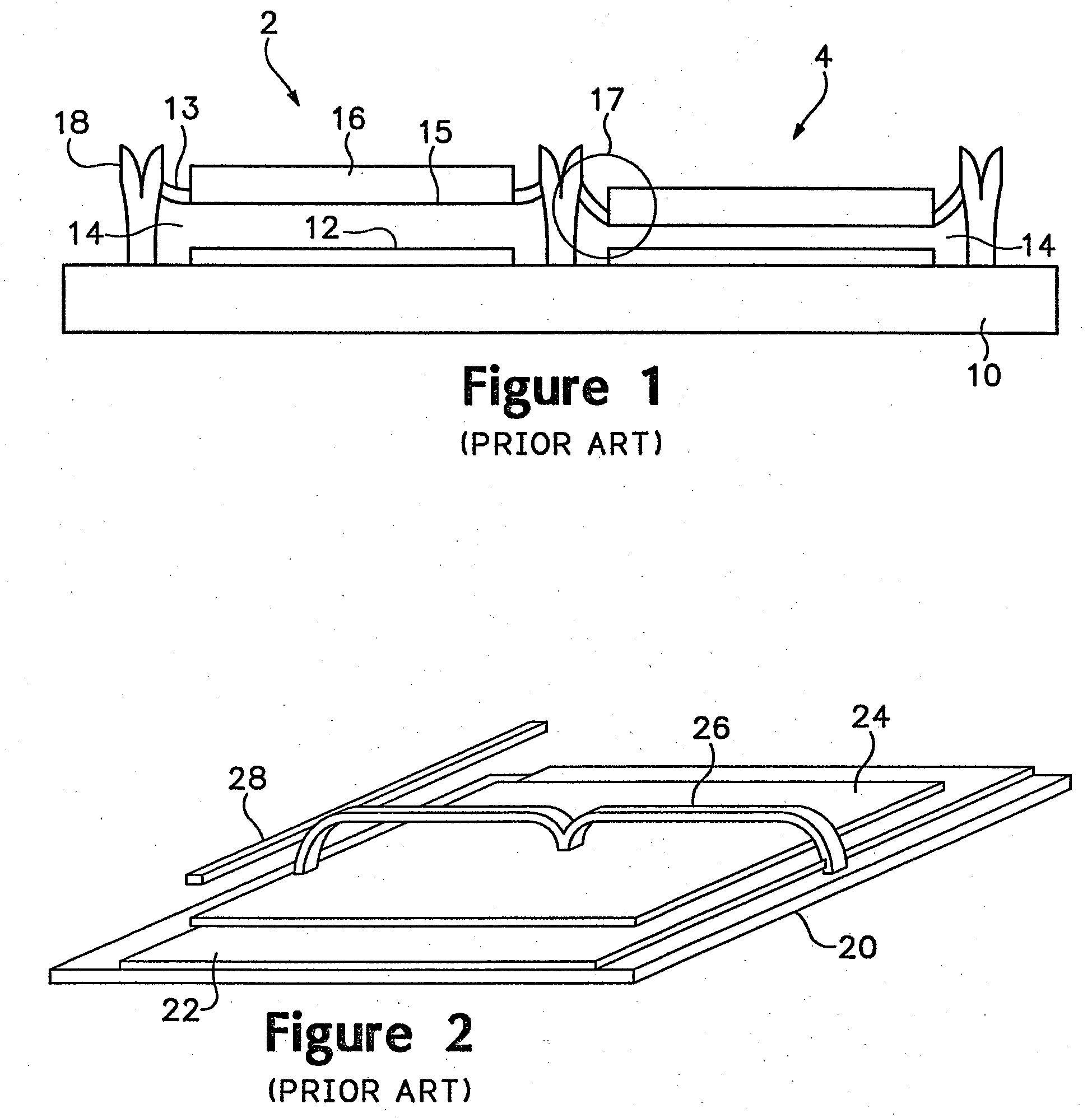
[0023]FIG. 1 shows a side view of an interferometric modulator. The modulator 2 is arranged on a transparent substrate 10, which is typically glass. A primary mirror 12 is arranged on top of an electrode that allows for addressing of individual elements of an array of interferometric modulators. Suspended above a cavity 14 is a secondary mirror 16, which rests upon, or is part of, a membrane 15. Support arms such as 13 may be part of the same layer as the membrane 15, support the mirror 16 and attach it to the support posts 18. The support arms and the membrane 15 are flexible. This allows the secondary mirror 16 to be moved into the cavity 14, bringing it closer to the primary mirror and thereby affecting the interference properties of the cavity.

[0024]Generally, the secondary mirror assumes a quiescent state in which it is away from the primary mirror, which may also be referred to as the ‘white’ state or the far position. It must be understood that the “white,” or ON, state may b...


PUM

PropertyMeasurementUnit
flexibleaaaaaaaaaa
insulatingaaaaaaaaaa
dimensionaaaaaaaaaa

Abstract

A separable modulator architecture is disclosed. The modulator has a mirror suspended from a flexible layer over a cavity. The flexible layer also forms supports and support posts for the mirror. An alternative separable modulator architecture has a mirror suspended over a cavity. The modulator is supported by supports and support posts. The support posts comprise a flexible layer over support post plugs. A bus structure may be formed upon the flexible layer arranged over the support posts.

Description

CROSS-REFERENCE TO RELATED APPLICATIONS[0001]This application is a continuation of U.S. patent application Ser. No. 10 / 644,312, filed Aug. 19, 2003, which is a continuation-in-part of U.S. patent application Ser. No. 10 / 078,282, filed Feb. 19, 2002, now U.S. Pat. No. 7,042,643, which is a divisional of U.S. patent application Ser. No. 09 / 991,378 filed on Nov. 21, 2001, which is a continuation of U.S. patent application Ser. No. 08 / 769,947 filed on Dec. 19, 1996, now abandoned.BACKGROUND OF THE INVENTION[0002]Spatial light modulators used for imaging applications come in many different forms. Transmissive liquid crystal device (LCD) modulators modulate light by controlling the twist and / or alignment of crystalline materials to block or pass light. Reflective spatial light modulators exploit various physical effects to control the amount of light reflected to the imaging surface. Examples of such reflective modulators include reflective LCDs, and digital micromirror devices (DMD™).[00...

Claims


Application Information

Patent Timeline
Patent Type & Authority Applications(United States)
IPC IPC(8): G02B26/00G02F1/21G01J3/26G02B6/12G02B26/02G02B26/08G02F1/137G09G3/34
CPCB82Y20/00G01J3/26G02B6/12G02B26/001G09G3/3466G02F1/13725G02F1/216G02F2203/03G02B2006/12104G02B26/00
Inventor SAMPSELL, JEFFREY BRIANMILES, MARK W.CHUI, CLARENCEKOTHARI, MANISH
Owner SNAPTRACK
Why Eureka
Try Eureka