Flow power converter apparatus employing a flow-controlled duct to capture flow energy

a flow control and flow converter technology, applied in the direction of machines/engines, final product manufacturing, electric generator control, etc., can solve the problems of low wave power generation, large rotating machines such as turbines equipped with generators, and cost more than a number of smaller machines with a corresponding total capacity, and achieve low manufacturing costs, simple robust operation, and low maintenance costs

Active Publication Date: 2009-04-16
STERNITZKE DONALD ALAN
View PDF18 Cites 14 Cited by
  • Summary
  • Abstract
  • Description
  • Claims
  • Application Information

AI Technical Summary

Benefits of technology

[0016]It is a purpose of the apparatus of this invention to provide flow power converter apparatus employing surge energy capture for converting useful wave surge energy over a relatively broad range of surf conditions, including relatively calm surf conditions and abnormally higher surf conditions. It is an advantage of the apparatus of this invention that some energy may be captured from low surf and more energy may be captured from higher surf without the need for adjusting the apparatus. It is a feature of the apparatus of this invention that the storage chamber and flow-controlled duct are disposed to capture and convert a signific

Problems solved by technology

Wave power as a means of generating electricity has been the focus of low-key study in the US and Europe for over thirty years, but with little public support.
Wave power generation is not a widely employed technology.
However, a large rotating machine, such as a turbine equipped with a generator, costs more than a number of smaller machines with a corresponding total capacity.
Complex systems such as hydraulic control systems, are not well suited to incremental implementation (do not sca

Method used


Image

  • Flow power converter apparatus employing a flow-controlled duct to capture flow energy
  • Flow power converter apparatus employing a flow-controlled duct to capture flow energy
  • Flow power converter apparatus employing a flow-controlled duct to capture flow energy

Examples


embodiment 10

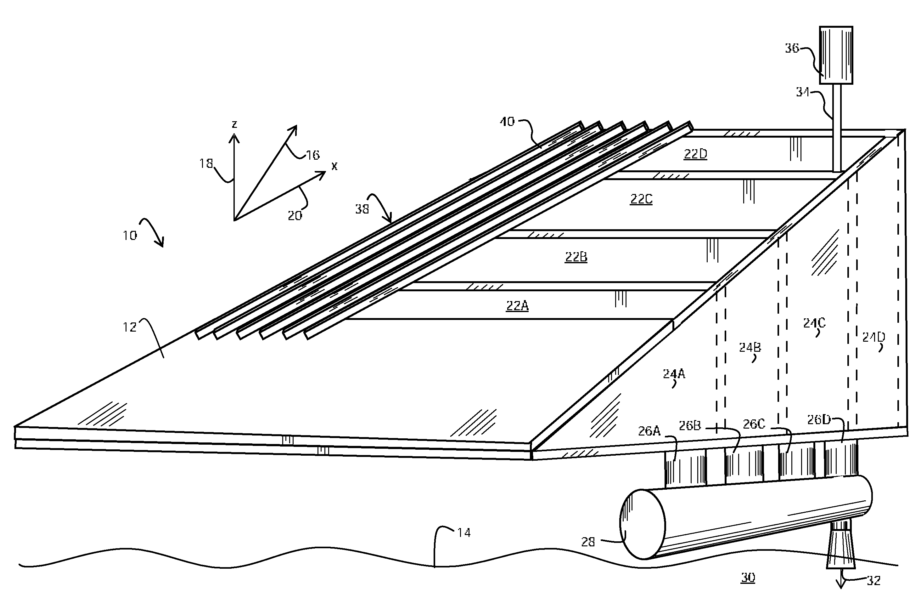
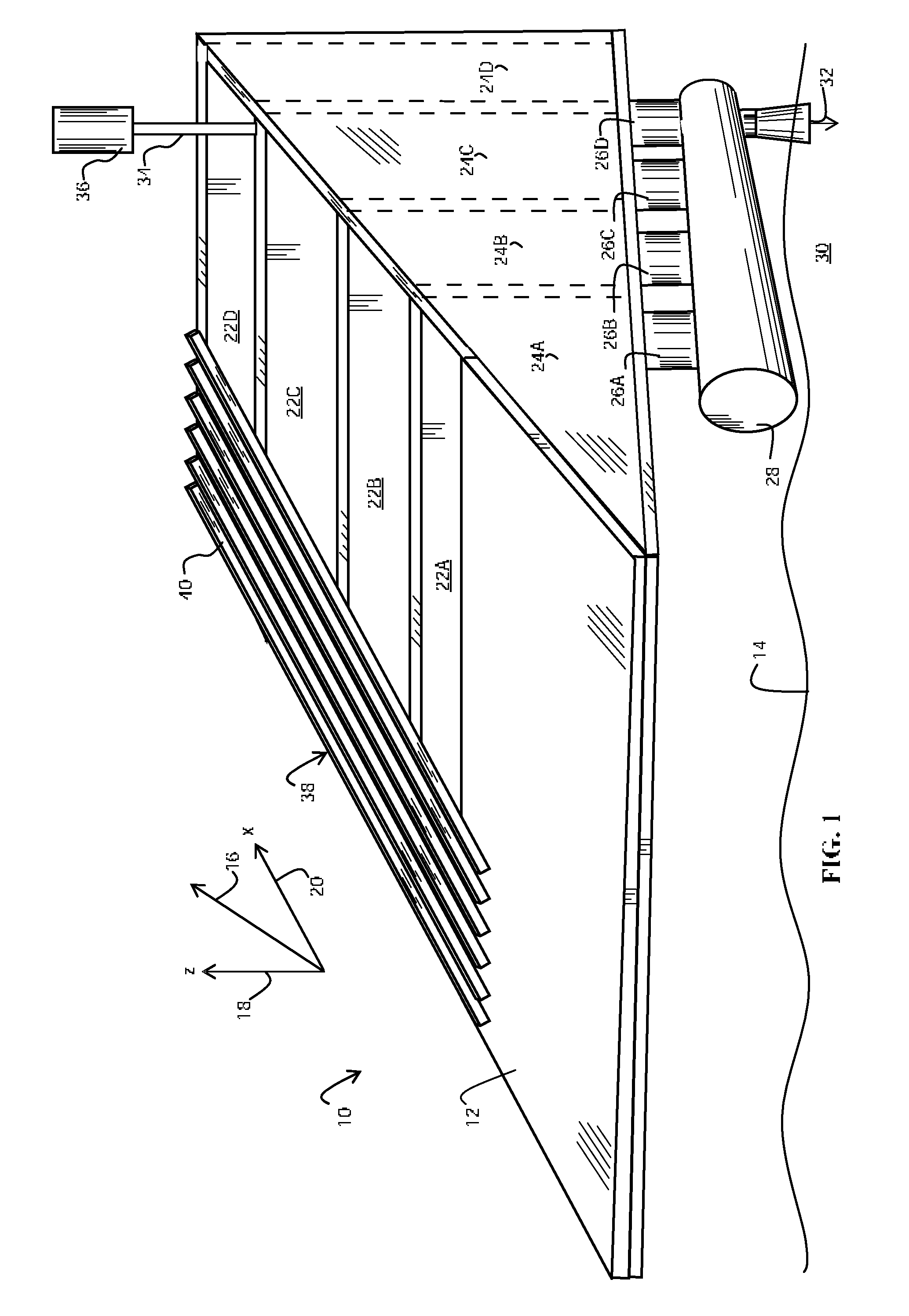
[0038]FIG. 1 illustrates a first wave surge power converter embodiment 10 of this invention, showing the inclined ramp 12. During operation, converter 10 is preferably disposed at an ocean surface 14 having episodic wave surges generally oriented in the direction indicated by the arrow 16 such that a typical wave surges vertically generally along the vertical surge component 18 and horizontally generally along the horizontal surge component 20. Ramp 12 is shown with a slope of about 33% (17-18 degrees) and is preferably oriented generally along surge direction 16 such that the wave surge water moves up ramp 12, progressing along a series of openings 22A-D therein. Each of openings 22A-D that is thereby exposed to the wave surge then receives surge water into the associated one of the plurality of independent chambers 24A-D. Each of the first independent chambers 24A-C is substantially isolated hydraulically from its neighbors by means of a single check valve (described below in conn...

embodiment 100

[0058]FIG. 6A illustrates a side view of an alternative wave surge power converter apparatus embodiment 100 showing the plurality of drain assemblies 126A-D and exemplary dispositions of the check valves 148A-C during normal flow conditions, which occur when ocean surface 14 remains below the highest of the independent chamber hydraulic heads 157A-D while remaining above the exit of the draft tube 132 to maintain siphon head through the turbine 146. Converter 100 includes a shaft 134 for coupling turbine 146 to a generator 136 but also provides an additional reversible transmission 166 to facilitate uninterrupted power conversion during backflow conditions that are now described.

[0059]Backflow conditions may arise whenever the ocean surface 114 rises and remains above one or more of independent chamber hydraulic heads 157A-D so that water is urged up through the draft tube 132, backing up through turbine 146, and into the conduit 128. Backflow operation should not be necessary for m...

embodiment 200

[0069]Converter embodiment 200 offers several advantages. The lack of interior walls in storage chamber 218 increases its storage capacity, minimizes interior wall maintenance (e.g., scraping barnacles) and permits the use of a larger diameter for low-head turbine 226. The float valve embodiment exemplified by float valve flap 217B (FIG. 9) minimizes valve friction head loss, thereby increasing the hydraulic head 225, which increases the output power proportionately with the hydraulic head raised to the three-halves power; [generator power] is proportional to [turbine head].3 / 2 Because the interior head 220 of the captured surge water is uniform throughout storage chamber 218, low-head turbine 226 may be disposed anywhere in the base 241 without loss of output power. In fact, base 241 provides room to dispose several low-flow turbines (not shown) operating under the same head, thereby optimizing output power, which is proportional to the total turbine area.

[0070]FIG. 10A is a schema...


PUM


Abstract

A wave power converter employing a flow-controlled duct for capturing and converting useful wave surge energy to electric power over a relatively broad range of surf or river flow conditions. The power converter includes an inclined ramp with several openings for receiving wave or river water and retaining surge water in hydraulic isolation, permitting water to flow into a flow-controlled conduit and a generator for producing electrical power from water flow in the conduit. The power converter apparatus is suitable for low-cost manufacture, offers simple robust operation suitable for underdeveloped regions of the world, may be fabricated from commonly-available components, requires few moving parts and no valuable (lootable) components other than a generator, and is self-flushing for low maintenance operation.

Description

CROSS-REFERENCE TO RELATED APPLICATIONS[0001]This application is filed under 37 C.F.R. §1.53(b) as a Continuation-In-Part of U.S. patent application Ser. No. 11 / 847,778 filed on Aug. 27, 2007 by the same inventor and now issued as U.S. Pat. No. ______ on ______.BACKGROUND OF THE INVENTION[0002]1. Field of the Invention[0003]This invention relates generally to a flow power converter and more particularly to a flow power converter employing a flow-controlled duct to capture both vertical and horizontal components of surge energy from overtopping waves and river flows.[0004]2. Description of the Related Art[0005]Wave power as a means of generating electricity has been the focus of low-key study in the US and Europe for over thirty years, but with little public support. Wave energy flux arises primarily from wind friction at the sea surface and is entirely distinct from the diurnal flux of tidal energy arising from the lunar cycle and from the steady flow of the major ocean currents ari...

Claims


Application Information

Patent Timeline
IPC IPC(8): F03B13/22
CPCF03B13/145Y02E10/38Y02E10/28F05B2250/314Y02E10/30Y02P70/50Y02E10/20
Inventor STERNITZKE, DONALD
Owner STERNITZKE DONALD ALAN
Why Eureka
Try Eureka