Optical disc, its reproducing device, recording device, manufacturing method, and integrated circuit

Inactive Publication Date: 2009-04-16
PANASONIC CORP
View PDF3 Cites 26 Cited by
  • Summary
  • Abstract
  • Description
  • Claims
  • Application Information

AI Technical Summary

Benefits of technology

[0150]With the optical disc, the manufacturing method, recording device, and reproducing device for the same, and the integrated circuit for the same, it is possible to provide an optical disc recorded with identification information in which a recording mark is formed in the second recording layer of the optical disc, which has a first recording layer and a second recording layer, at substantially the same position as the track position of the first recording layer.
[0151]Thus, it is not possible to perform tracking control onto the second recording mark and copy it if the second recording mark is recorded at a frequency that is outside of the normal tracking control band.
[0152]Further, even if a frequency that is outside of tracking by the servo is not used, it is still necessary to switch the focal position from the first recording layer within the range of one track of the second recording layer, and thus in practical terms it is difficult to track onto the second recording mark and therefore the recording mark of the second recording layer cannot be copied.
[0153]Since the recording mark of the second recording layer is reproduced after a minute change in the modulation when reproducing the first recording layer, if this minute change in the first modulatio

Problems solved by technology

Copyright protection of the digital copyrighted material that is recorded is one matter that becomes an issue here.
Such encoding technology, however, is applicable only when the key remains secret, and the copyright of the copyrighted material cannot be protected once the key information is leaked.
At the present time, such illegal copying techniques have hurt the distribution of ordinary copyrighted material on CD and DVD, resulting in significant loss.
Although t

Method used


Image

  • Optical disc, its reproducing device, recording device, manufacturing method, and integrated circuit
  • Optical disc, its reproducing device, recording device, manufacturing method, and integrated circuit
  • Optical disc, its reproducing device, recording device, manufacturing method, and integrated circuit

Examples


first embodiment

1. Optical Disc

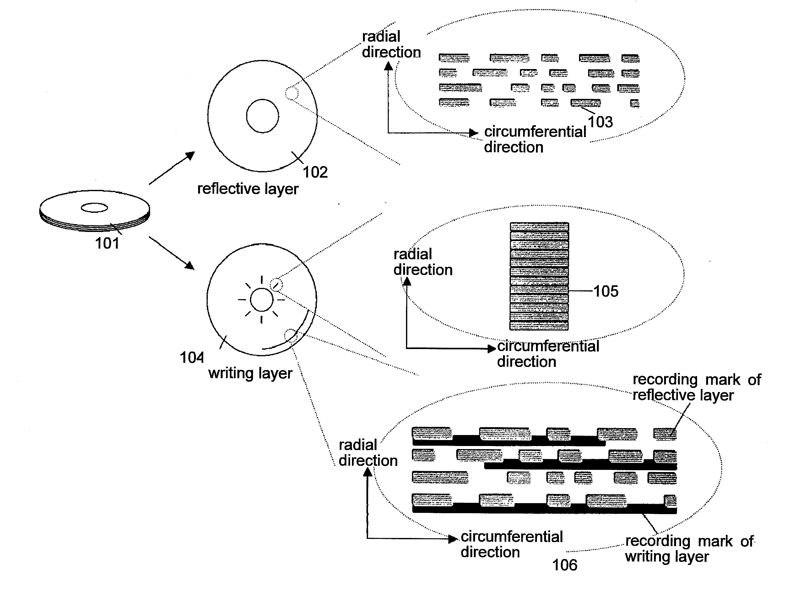
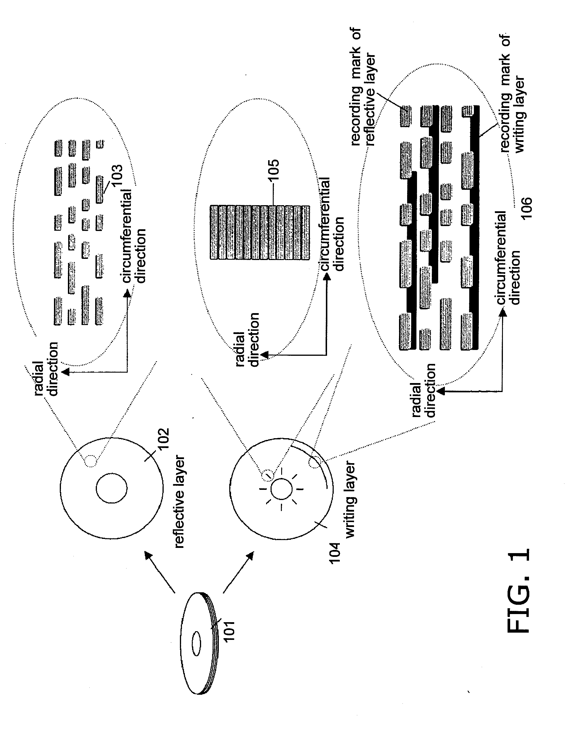
[0212]FIG. 1 is a conceptual diagram of the optical disc according to this embodiment. An optical disc 101 has a reflective layer on which primary information is recorded by forming a reflective film made of aluminum or silver, for example, over unevenly shaped recording marks, and a writing layer that can be written to by irradiating a laser onto a layer that is behind from or at the side which is irradiated with the laser for reading the unevenly shaped marks.

[0213]A reflective layer 102 of the optical disc is a recording layer that is equivalent to the information recording layer on an ordinary read-only disc. Information is recorded to the reflective layer 102 by forming unevenly shaped recording marks 103 in a continuous fashion in the circumferential direction.

[0214]The information that is recorded by the recording marks is various digital information such as voice / video information, game information, or data.

[0215]When information is to be reproduced from the r...

second embodiment

1. Optical Disc

[0426]In this embodiment, an optical disc having a writing layer that includes a pre-mark recording region in which pre-marks are formed and a wobble region in which a wobble that includes address information is formed, and a reflective layer that is behind or in front of the writing layer primarily on which content information that includes address information is recorded through uneven marks, and a process for manufacturing that disc and a device for reproducing that disc, are described in detail using the drawings.

[0427]FIG. 19 is a conceptual diagram of the optical disc according to this embodiment. The optical disc has a reflective layer on which primarily content information is recorded as uneven marks, and a writing layer that is behind or in front of the reflective layer and that includes a pre-mark recording region in which pre-marks are recorded and a wobble region in which a wobble including address information is formed. The disc 1601 is made of at least a...

third embodiment

[0548]Next, a third embodiment of the invention is described in detail using the drawings.

[0549]This embodiment is a method that uses the position information recording device and the position information reproducing device according to the first embodiment, and increases resistance against more clever, unauthorized analysis, by a third party with ill intent, of the content that was disclosed in the first embodiment, by scrambling or performing PE modulation, and then recording, the position information that is recorded to the disc writing layer.

[0550]FIG. 24 is a characteristic block diagram of the position information record control portion according to this embodiment, and this corresponds to the position information record control portions 508 and 908 according to the first embodiment.

[0551]The position information record control portion receives the PLL clock from the digital signal processing portion 506 / 906, and the synchronization code detection timing and addresses from the...


PUM


Abstract

An optical disc (101) to and from which information can be reproduced and recorded by laser irradiation is provided with a first recording layer (102) and a second recording layer (104). The first recording layer (102) has a first recording mark (103) that is formed in a spiral track. The second recording layer (104) is behind or in front of the read-side surface of the first recording layer (102), and neither a wobble track nor a track for reproducing or recording information by laser irradiation is formed on the second recording layer (104). On the second recording layer (104) are formed, by laser irradiation, a second recording mark (105) that is positioned in the radial direction of the optical disc according to a predetermined position on the spiral track of the first recording layer. The optical disc (101) ensures the secrecy of the copyright protected information that is recorded thereto and the copyright protection function of the optical disc (101), and is resistant against illegal copying.

Description

TECHNICAL FIELD[0001]The present invention relates to optical discs, reproducing devices, recording devices, and manufacturing methods for the same, and integrated circuits for the same. In particular, it relates to optical discs that have information for copyright protection and that function (referred to hereinafter as copyright protection information and copyright protection function), devices for reproducing the same, devices for recording the same, methods for manufacturing the same, and integrated circuits for the same.BACKGROUND ART[0002]At the present moment, there has been remarkable growth in the memory capacity of optical discs. In particular, Blu-ray discs, which are recorded and reproduced using a blue laser, can achieve tremendously large memory capacities on the order of 25 G bytes for single layered and 50 G bytes for double layered discs, allowing more than four hours of high-quality, high-definition video to be recorded. This increase in capacity per disc is expect...

Claims


Application Information

Patent Timeline
IPC IPC(8): G11B7/00G11B7/24G11B7/24038G11B7/24041G11B7/24094G11B7/24097
CPCG11B7/00456G11B2220/2541G11B7/24038G11B7/2405G11B20/00086G11B20/00586G11B20/00601G11B20/00688G11B20/1217G11B2020/1238G11B2020/1239G11B2020/1287G11B2220/235G11B2220/237G11B7/00736
Inventor YAMAOKA, MASARUSHOJI, MAMORUKONDO, KENJINISHIKIORI, KEIJI
Owner PANASONIC CORP
Why Eureka
Try Eureka