
Adjustable alignment golf putter

a golf putter and adjustment technology, applied in the field of adjustable alignment golf putters, can solve the problems of compounding the putting error, causing golfers to misalign the putt, and not providing the maximum alignment efficiency for a shorter golfer

Inactive Publication Date: 2009-05-07
ROENICK HARRY ANTHONY
View PDF29 Cites 33 Cited by
  • Summary
  • Abstract
  • Description
  • Claims
  • Application Information

AI Technical Summary

Benefits of technology

"The present invention is an adjustable alignment golf putter that helps golfers correct or compensate for visual errors or misalignment between the intended or target line and the visualized or virtual putt line between the golf ball and cup. The putter has a lower putter head with a visual alignment means, including an alignment support or base and a visual alignment indicator movably disposed thereon. The visual alignment indicator comprises an elongated member with an alignment indicator guide to control its movement. The putter also has an indicator retention member to secure the visual alignment indicator in place. The adjustable alignment golf putter helps golfers align the putter face along the actual intended or target line and compensate for the perceived alignment due to eye predominance. Once properly aligned, the golfer can easily align the offset elongated member with the cup and stroke the putt down that line with no compensation for misalignment."

Problems solved by technology

Regardless, eye predominance commonly causes golfers to misalign putts.
Of course, other sources of visual misalignment such as convergence and triangulation can contribute to a golfer misaligning a putt.
The one-time sighting adjustment made to these clubs may be helpful for long putts, but such an adjustment does not provide a golfer with maximum alignment efficiency for shorter putts and may actually compound the putting error in distances shorter than, for instance, ten feet.

Method used


Image

  • Adjustable alignment golf putter
  • Adjustable alignment golf putter
  • Adjustable alignment golf putter

Examples


Embodiment Construction

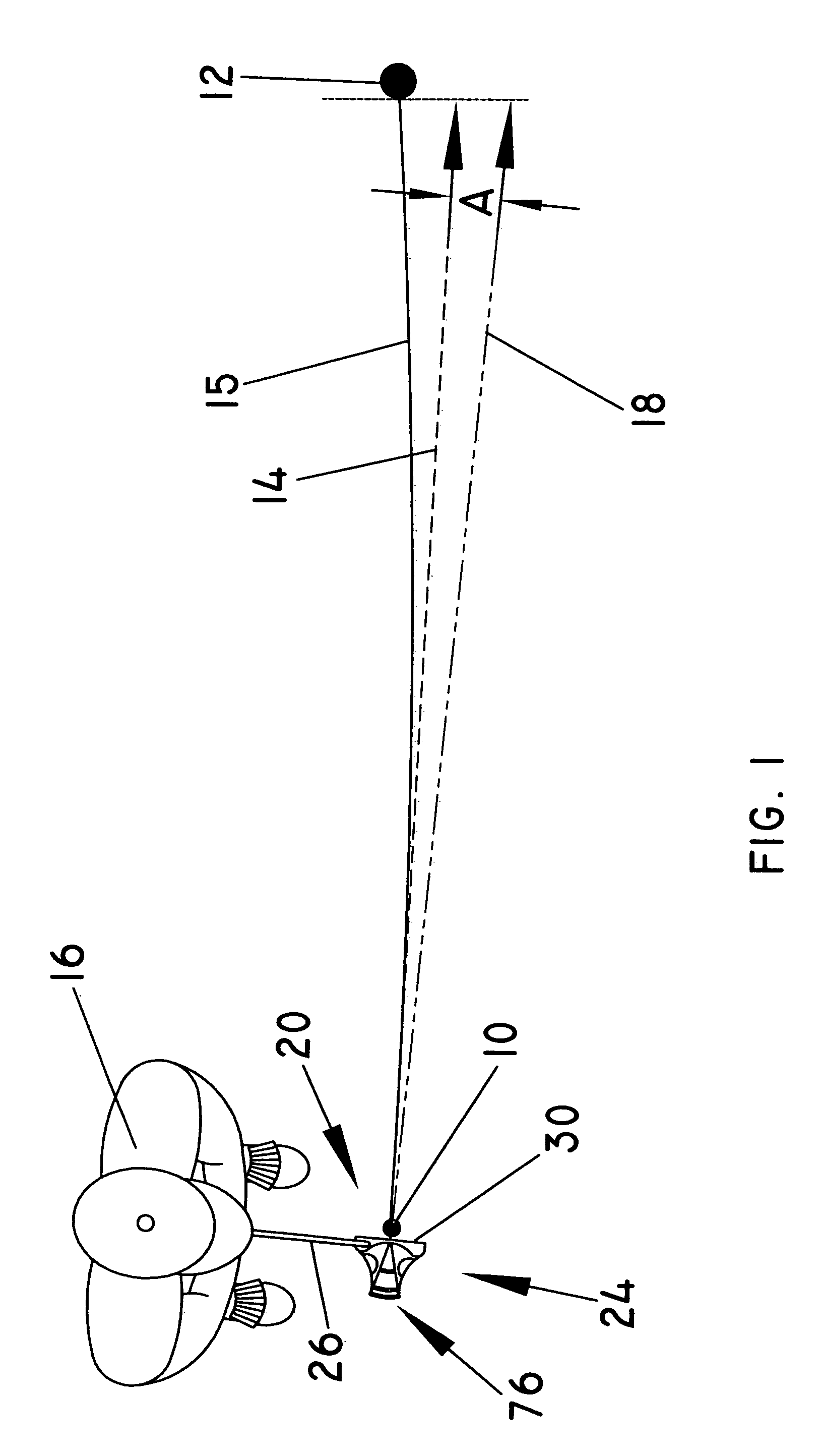
[0038]FIG. 1 illustrates the sighting error a golfer experiences due to eye predominance or other source of visual misalignment. Specifically, the intended or target line 14 between the golf ball 10 and the cup 12 is determined by the slope and contour of the green that when the golf ball 10 is stroked or putted properly, the golf ball 10 will follow the putt line 15. However, the golfer 16 views or sees the intended or target line 14 as a visualized putt line 18 offset thereto by angle A. As described hereinafter, the present invention relates to an adjustable alignment golf putter shown generally as 20 to correct or compensate for the visual error or misalignment of the true or actual putt line 14 and the virtual putt line 18.

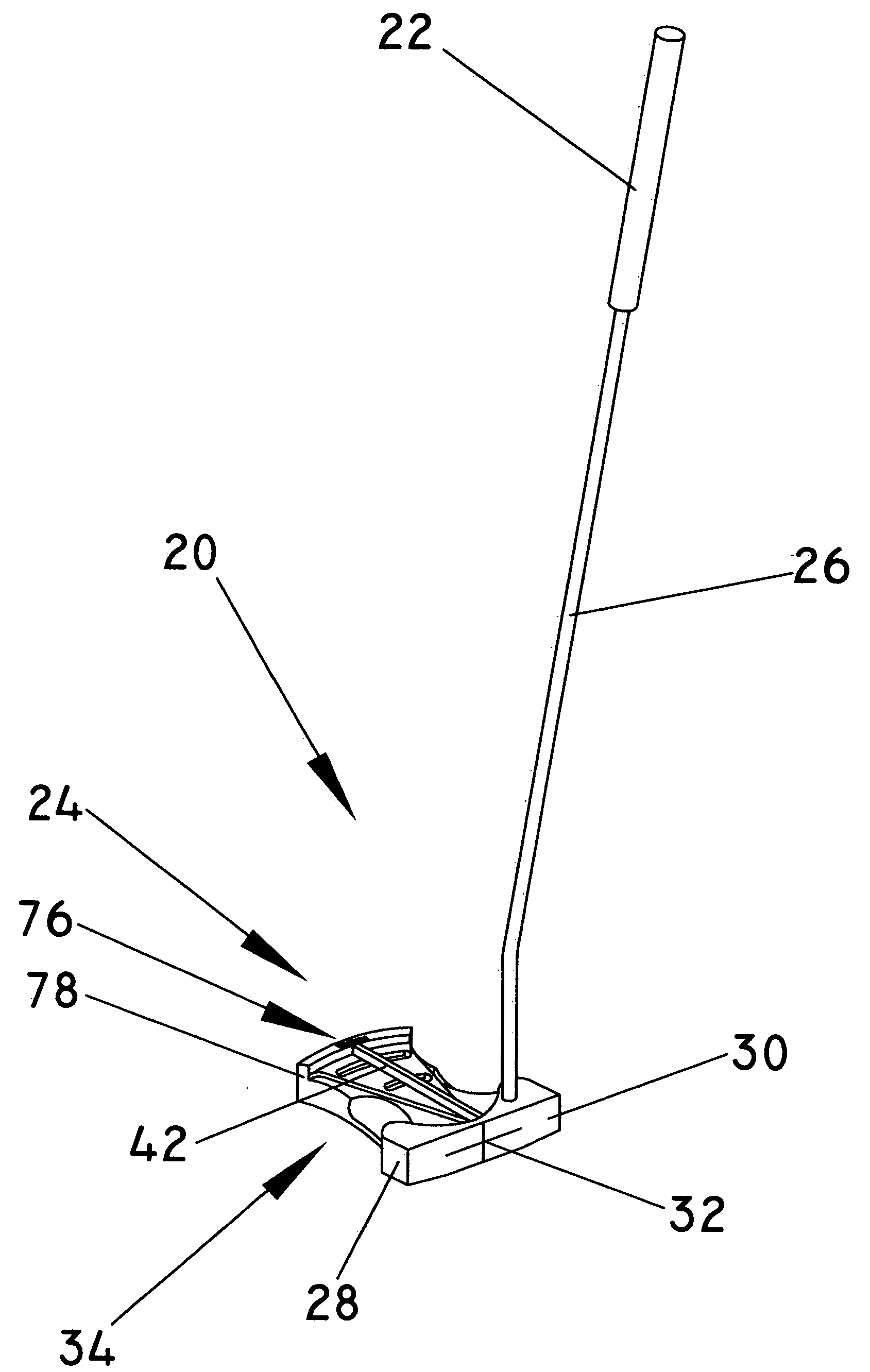
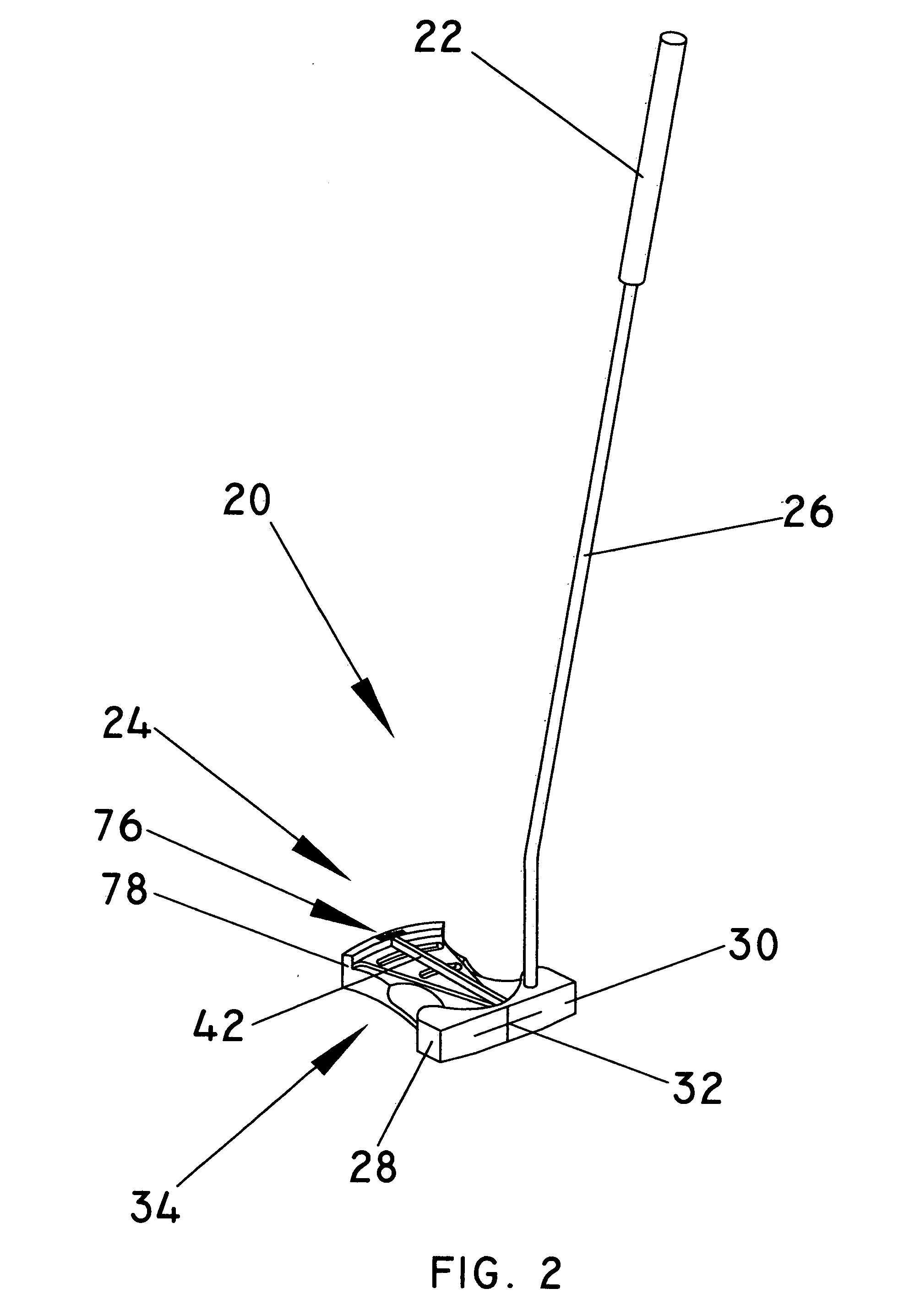
[0039]As shown in FIG. 2, the adjustable alignment golf putter 20 comprises an upper golf grip 22 and a lower putter head generally indicated as 24 attached to opposite end portions of a putter shaft 26.

[0040]As best shown in FIGS. 2 through 4, the lower putt...


PUM


Abstract

An adjustable alignment golf putter to compensate for a golfer's visual misalignment of the putter face due to eye predominance or other source of misalignment to the intended or target line taking into account the slope and contour of the green comprising an upper golf grip and a lower putter head attached to opposite end portions of a putter shaft, the putter head including a putter body having an outer putter face including a centrally disposed optimum contact point on one side thereof to strike a golf ball when putting and a visual alignment means formed on the side opposite the putter face, the visual alignment means including a visual alignment base to support an adjustable alignment element movably positioned thereon in operative disposition relative to the optimum contact point to selectively align the adjustable alignment element on a virtual intended or target line between the optimum contact point and the cup angularly off set relative to the intended or target line between the golf ball and cup to compensate for the golfer's visual misalignment when putting the golf ball along the intended line to the cup and an alignment element retention member to selectively secure the adjustable alignment element in position relative to the optimum contact point.

Description

CROSS-REFERENCE[0001]This is a utility application of co-pending provisional application Ser. No. 61 / 001,851 filed Nov. 5, 2007.BACKGROUND OF THE INVENTION[0002]1. Field of the Invention[0003]An adjustable alignment golf putter including an adjustable visual alignment indicia to correct or compensate for a golfer's visual misalignment of the putter face to the desired target line or intended line between the optimum contact point on the putter face and the cup.[0004]2. Description of the Prior Art[0005]Numerous golf putters designs have been developed in an effort to improve a golfer's putting accuracy. Such designs include curved-shafted putters, putters with shaft offsets and mallet-like putters.[0006]Regardless, eye predominance commonly causes golfers to misalign putts. Thus, a putter that allows a golfer to align the putt to the virtual line between the golf ball and cup with the putter face perpendicular to the line the golfer could stroke the golf ball along the actual line b...

Claims


Application Information

Patent Timeline
Patent Type & Authority Applications(United States)
IPC IPC(8): A63B53/06
CPCA63B49/06A63B2053/0441A63B53/08A63B53/0487A63B60/52A63B53/0441A63B60/00
Inventor ROENICK, HARRY ANTHONY
Owner ROENICK HARRY ANTHONY
Learn More