Energy storage device cell and control method thereof

a technology of energy storage device and control method, which is applied in the direction of secondary cell servicing/maintenance, cell components, sustainable manufacturing/processing, etc., can solve problems such as electrical characteristics deterioration

Active Publication Date: 2009-06-11
MITSUBISHI ELECTRIC CORP
View PDF4 Cites 74 Cited by
  • Summary
  • Abstract
  • Description
  • Claims
  • Application Information

AI Technical Summary

Benefits of technology

[0016]The present invention makes it possible to make the common anode including the anode collector foil having the through-hole operate as an anode for the capacitor cathode and battery cathode, and by sandwiching the two separators between the capacitor cathode and battery cathode, these cathodes can be physically remotely separated. By such a configuration, insertion of anions in the capacitor cathode and release of catio

Problems solved by technology

By such a configuration, insertion of anions in the capacitor cathode and release of cations from the battery cathode at the time of charging and release of anions from the capacitor cathode and insertion of anions in the battery cathode are completely separat

Method used


Image

  • Energy storage device cell and control method thereof
  • Energy storage device cell and control method thereof
  • Energy storage device cell and control method thereof

Examples


embodiment 1

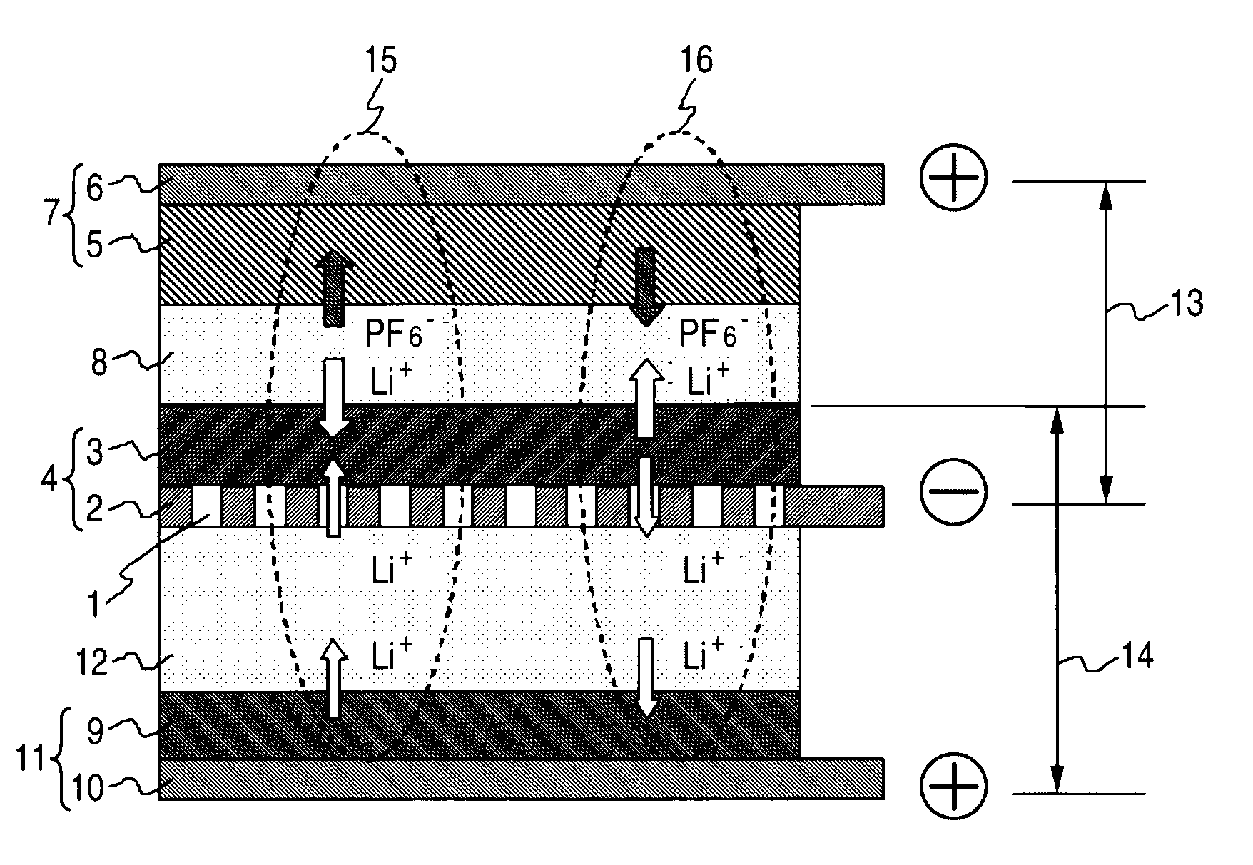
[0030]FIG. 1 is a sectional schematic view of an energy storage device cell according to Embodiment 1 for carrying out the present invention. A common anode 4 for which an anode electrode layer 3 is applied to one face of an anode collector foil 2 having through holes 1 and a capacitor cathode 7 for which a capacitor cathode electrode layer 5 containing activated carbon microparticles is applied to a capacitor cathode collector foil 6 are opposed via a first separator 8, and a battery cathode 11 for which a battery cathode electrode layer 9 of lithium ions containing microparticles of a lithium-containing metal compound is applied to a battery cathode collector foil 10 and a face of the anode collector foil 2 applied with no anode electrode layer 3 are opposed via a second separator 12.

[0031]The capacitor cathode 7, the first separator 8, and the common anode 4 construct a lithium ion capacitor 13, and the battery cathode 11, the second separator 12, and the common anode 4 construct...

embodiment 2

[0058]In Embodiment 2, characteristics of the energy storage device cell obtained in Embodiment 1 are compared with the characteristics of a conventional lithium ion battery.

[0059]FIG. 4A is a plan schematic view of the energy storage device cell according to the present embodiment and FIG. 4B is a sectional schematic view along A-A′. In FIGS. 4A and 4B, activated carbon (steam activated carbon) having an average particle diameter of 5 μm, an SBR binder, ammonium CMC (a thickener), and carbon black (an electrical conductor) were mixed into water to be a paste, and the paste was applied by means of a doctor blade on the surface of an aluminum foil having a thickness of 20 μm serving as a capacitor cathode collector foil 6 so as to become a capacitor cathode electrode layer 5, dried, and then pressed to form a capacitor cathode 7. The thickness of the capacitor cathode electrode layer 5 after pressing was provided as 100 μm.

[0060]Although a battery cathode 11 was fabricated by the sam...

embodiment 3

[0076]FIG. 8A is a plan view of an energy storage device cell according to Embodiment 3 of the present invention and FIG. 8B is a sectional schematic view along B-B′. In the present embodiment, four combinations of the paired electric double layer capacitor and lithium ion battery of Embodiment 1 are placed one upon another. In FIGS. 8A and 8B, the capacitor cathode collector foil and the battery cathode collector foil in a laminated part are formed by a single common cathode collector foil 27. Further, in a laminated uppermost portion and lowermost portion, an electrical insulating sheet 28 is arranged between the aluminum laminated container 17 and the capacitor cathode collector foil and battery cathode collector foil. For the electrical insulating sheet 28, polyethylene terephthalate having a thickness of approximately 0.2 mm can be used, for example.

[0077]In the energy storage device cell thus constructed, since four combinations of the paired electric double layer capacitor an...


PUM


Abstract

An energy storage device cell includes: a capacitor cathode including a capacitor cathode collector foil, and a capacitor cathode electrode layer formed on one face of the capacitor cathode collector foil and containing microparticles of activated carbon; a first separator; a common anode including an anode collector foil having a through-hole, and an anode electrode layer formed on one face of the anode collector foil; a second separator; and a battery cathode including a battery cathode collector foil, and a battery cathode electrode layer formed on one face of the battery cathode collector foil and containing particles of a lithium-containing metal compound. The first separator is sandwiched by the capacitor cathode electrode layer and the anode electrode layer. The second separator is sandwiched by the anode collector foil and the battery cathode electrode layer.

Description

CROSS-REFERENCE TO RELATED APPLICATIONS[0001]This application is based upon and claims the benefit of priority from Japanese Patent Application No. 2007-316844, filed Dec. 7, 2007, the entire contents of which are incorporated herein by reference.BACKGROUND OF THE INVENTION[0002]1. Field of the Invention[0003]The present invention relates to an energy storage device cell with a built-in configuration of a lithium ion capacitor and a lithium ion battery and a control method thereof.[0004]2. Description of the Related Art[0005]Energy storage device cells include electric double layer capacitors, lithium ion batteries, and lithium ion capacitors. An electric double layer capacitor (also simply called a capacitor, a super capacitor, an electrochemical capacitor, or the like, and a lutetium ion capacitor to be described later is also inclusively referred to as a capacitor), is provided with polarizable electrodes (a cathode and an anode) mutually facing across a separator, and makes use ...

Claims


Application Information

Patent Timeline
IPC IPC(8): H01M2/14H01G11/06H01G11/22H01G11/42H01G11/52H01G11/66H01G11/70H01M4/13H01M4/133H01M4/58H01M4/583H01M4/66H01M4/70H01M10/058H01M10/0585H01M10/0587H01M10/44H01M50/417H01M50/423H01M50/426H01M50/429H01M50/491
CPCH01G9/058H01G9/155H01G11/42H01M2/1653H01M4/02H01M4/5825Y02E60/122H01M4/667H01M10/0525H01M10/44H01M12/005Y02E60/13H01M4/583Y02E60/10Y02P70/50H01G11/50H01G11/06H01G11/46H01G11/70H01G11/08H01M50/429H01M50/417H01M50/491H01M50/423H01M50/426H01G11/22
Inventor MITSUDA, KENROHIROI, OSAMUTAKEMURA, DAIGOAIHARA, SHIGERU
Owner MITSUBISHI ELECTRIC CORP
Why Eureka
Try Eureka