Foldable chair frame

a folding chair and frame technology, applied in the field of chair frames, can solve the problems of wasting materials, enhancing cost, and inability to operate, and achieve the effect of enhancing cost and being able to opera

Inactive Publication Date: 2009-07-09
CHEN KAO SAN
View PDF5 Cites 19 Cited by
  • Summary
  • Abstract
  • Description
  • Claims
  • Application Information

AI Technical Summary

Problems solved by technology

Therefore, such design has the disadvantages such as not being able to match the ergonomic problem, wasting material and enhancing the cost.

Method used


Image

  • Foldable chair frame
  • Foldable chair frame
  • Foldable chair frame

Examples


Embodiment Construction

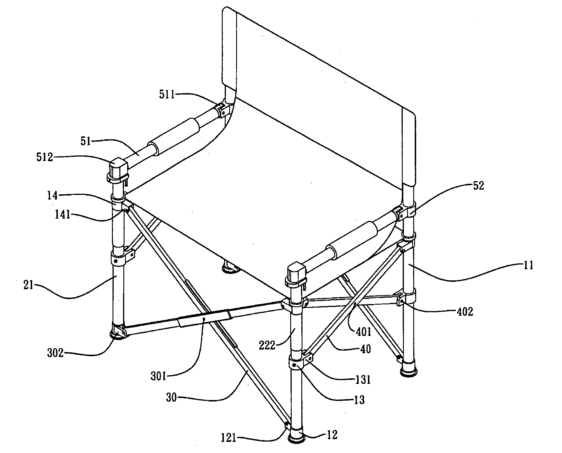
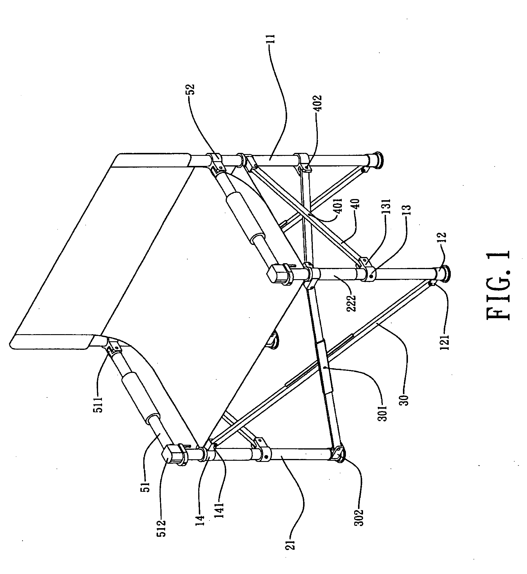
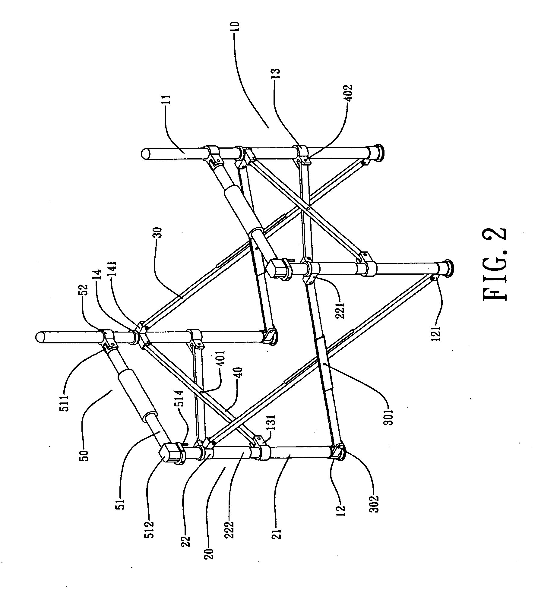
[0016]Please refer to FIGS. 1 through 7, the preferred embodiment of the foldable chair frame which is in rectangular shape when being unfolded is shown to comprise rear rod units (10), front leg rod units (20), cross-shaped long leg members (30), cross-shaped short leg members (40) and movable armrest units (50).

[0017]The rear leg rod unit (10) comprises a pair of rear leg rod members (11), each of which is in cylinder shape, base caps (12), which are respectively installed with a pivot bracket (121) for engaging with the cross-shaped long leg members (30), receiving caps (13) and receiving cap base of the rear legs (14). The receiving caps (13) which are respectively installed with pivot brackets (131) for engaging with cross-shaped short leg member (40). The receiving cap bases of the rear legs (14) which are respectively installed with a pivot bracket (141) for engaging with cross-shaped long leg members (30) and cross-shaped short leg members (40).

[0018]The front leg rod unit (...


PUM


Abstract

A foldable chair frame includes front leg rod units, rear leg rod units, cross-shaped long leg members, cross-shaped short leg members and movable armrest unit. The front leg rod unit includes a pair of front leg rod members, base caps, receiving caps and receiving cap base of the front leg. The rear leg rod unit includes a pair of rear leg rod members, base caps, receiving caps and receiving cap base of the rear leg. The cross-shaped long leg members and cross-shaped short leg members are in bar shape and have pin holes being installed respectively at the central part and each ends thereof. The movable armrest unit includes a pair of main shaft and fixing caps.

Description

BACKGROUND OF THE PRESENT INVENTION[0001]1. Field of the Invention[0002]The present invention relates to a chair frame, particularly to a cross-shaped foldable chair frame.[0003]2. Description of the Related Arts[0004]As shown in FIG. 8, the conventional foldable chair is shown to comprise crossed-shaped front, rear, left and right leg unit which are equal in length. Therefore the shape is shown to be square when the chair is completely in unfolded position. However, people usually need larger frontal than lateral space when seat on the chair in concern of being ergonomic, which means that when the frontal space is enlarged, the lateral space will also definitely be enlarged. Therefore, such design has the disadvantages such as not being able to match the ergonomic problem, wasting material and enhancing the cost.SUMMARY OF THE PRESENT INVENTION[0005]Please refer to FIGS. 1, 2, 3 and 4, the inventors has improved the design in view of the shortcomings of the prior art. The present i...

Claims


Application Information

Patent Timeline
Patent Type & Authority Applications(United States)
IPC IPC(8): A47C4/00
CPCA47C4/286
Inventor CHEN, KAO-SAN
Owner CHEN KAO SAN
Why Eureka
Try Eureka