

Distributed power architecture having centralized control unit
a technology of centralized control unit and distributed power, which is applied in the direction of dc network circuit arrangement, hot plugging-unplugging power/load, ac network voltage adjustment, etc., can solve the problem of low power distribution loss, and achieve the effect of less space, less elements, and higher efficiency
- Summary
- Abstract
- Description
- Claims
- Application Information
AI Technical Summary
Benefits of technology
Problems solved by technology
Method used
Image

Examples
Embodiment Construction
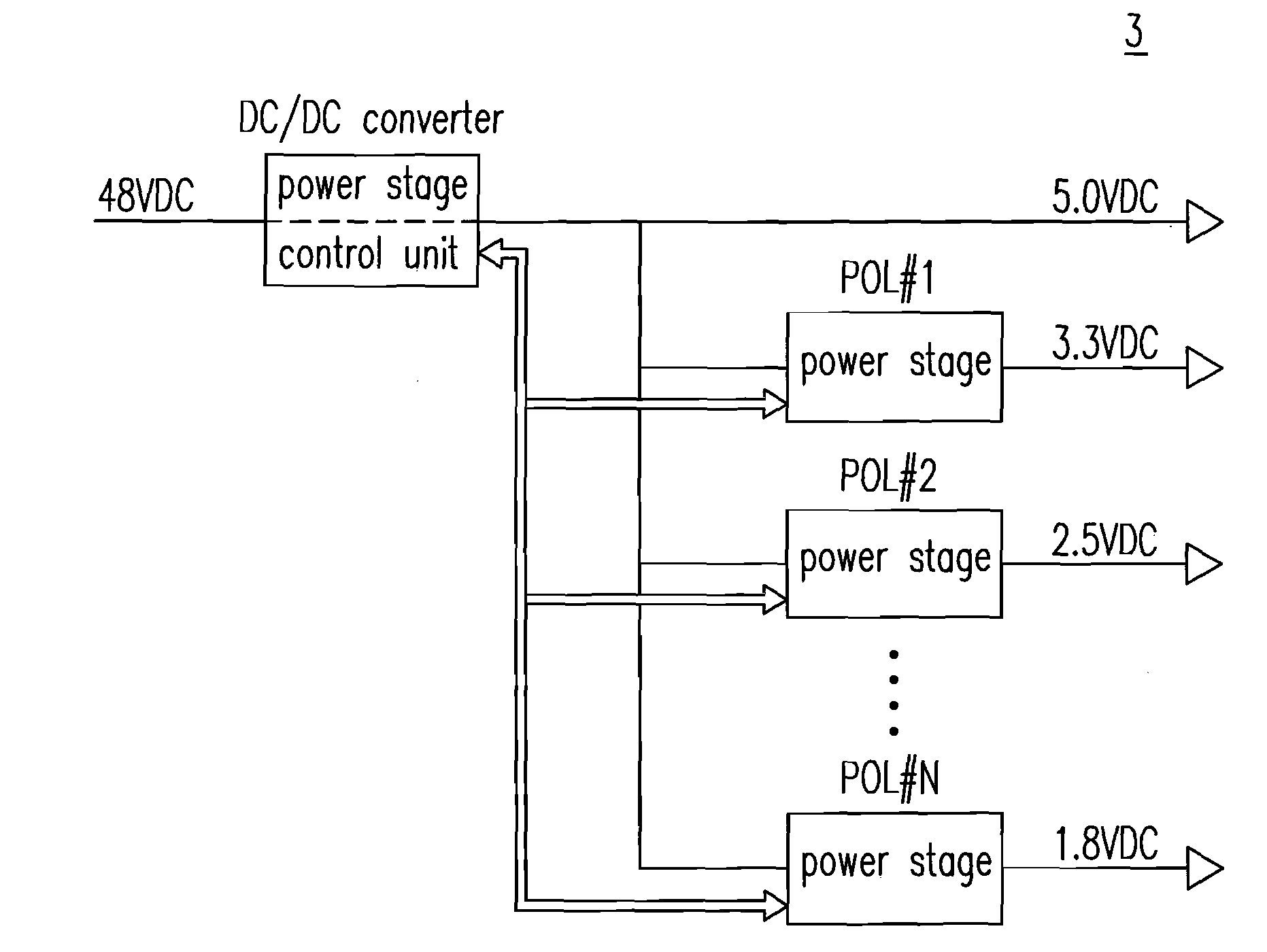
[0034]FIG. 5(a) shows a schematic circuit diagram of a DPA having a centralized control unit according to the first preferred embodiment of the present invention. In FIG. 5(a), a DPA 3 includes a DC / DC converter (it could be an independent DC / DC converter) receiving, e.g., but not limited to, a 48 VDC bus voltage and including a (first) power stage and a control unit (a centralized control unit) and a plurality of POL converters POL#1-POL#N. The DC / DC converter of the DPA 3 receives the 48 VDC input voltage and outputs a relatively lower, e.g., but not limited to a 5.0 VDC, output voltage (which is a bus voltage). The output voltage of 5.0 VDC is converted to, e.g., but not limited to 3.3 VDC, 2.5 VDC and 1.8 VDC, output voltages of the plurality of POL converters via a unified manipulation of the plural (second) power stages of the plurality of second converters through the centralized control unit. Each of the POL converters has the second power stage only but doesn't have its own...
PUM
 Abstract
Description
Claims
Application Information