

Electromagnetic induction type encoder
- Summary
- Abstract
- Description
- Claims
- Application Information
AI Technical Summary
Benefits of technology
Problems solved by technology
Method used
Image

Examples
embodiment 1
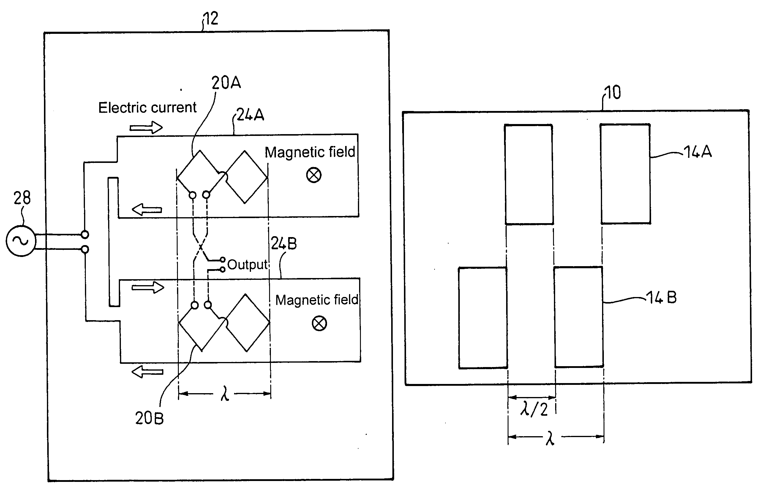
[0034]As shown in FIG. 4, Embodiment 1 of the present invention is such that transmitting coils 24A, 24B and the receiving coils 20A, 20B on the same grid 12 and scale coils 14A, 14B on the scale 10 are disposed by two sets each symmetrically with respect to the center of the scale 10, and scale coil 14A of one set is shifted by ½ phase of the scale pitch (λ) with respect to scale coil 14B of the other set.
[0035]The shapes of two sets of transmitting coils 24A, 24B and the receiving coils 20A, 20B are made common to each other, and are connected so that an electric current flows to the transmitting coils 24A, 24B in the same direction and a difference in signals of the receiving coils 20A, 20B is output.
[0036]As shown by the arrows in FIG. 4, where an electric current flows to the two transmitting coils 24A, 24B in the same direction, magnetic fields are brought about at the transmitting coils 24A, 24B in the same direction. Here, since the phases of the scale coils 14A, 14B are shi...
embodiment 2
[0037]Next, a description is given of Embodiment 2 of the present invention. The present embodiment is such that, as shown in FIG. 6, an electric current flows to the transmitting coils 24A, 24B in the reverse direction, and the transmitting coils 24A, 24B and the receiving coils 20A, 20B are connected so as to output the sum of signals of the receiving coils 20A, 20B.
[0038]As in the present embodiment, where an electric current is caused to flow to the transmitting coils 24A, 24B in the opposite direction, magnetic fields are brought about in the opposite direction, respectively. At this time, as shown in FIGS. 7(A) and (B), a signal for which offset having different polarities is given on the same waveform is obtained in the receiving coils 20A, 20B. Therefore, by connecting the receiving coils 20A, 20B so that the signals of the two receiving coils 20A, 20B are added to each other, it is possible to obtain a signal for which the offset is cancelled, as shown in FIG. 7(C).
[0039]Al...
PUM
 Abstract
Description
Claims
Application Information