
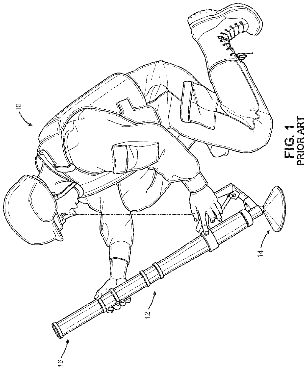
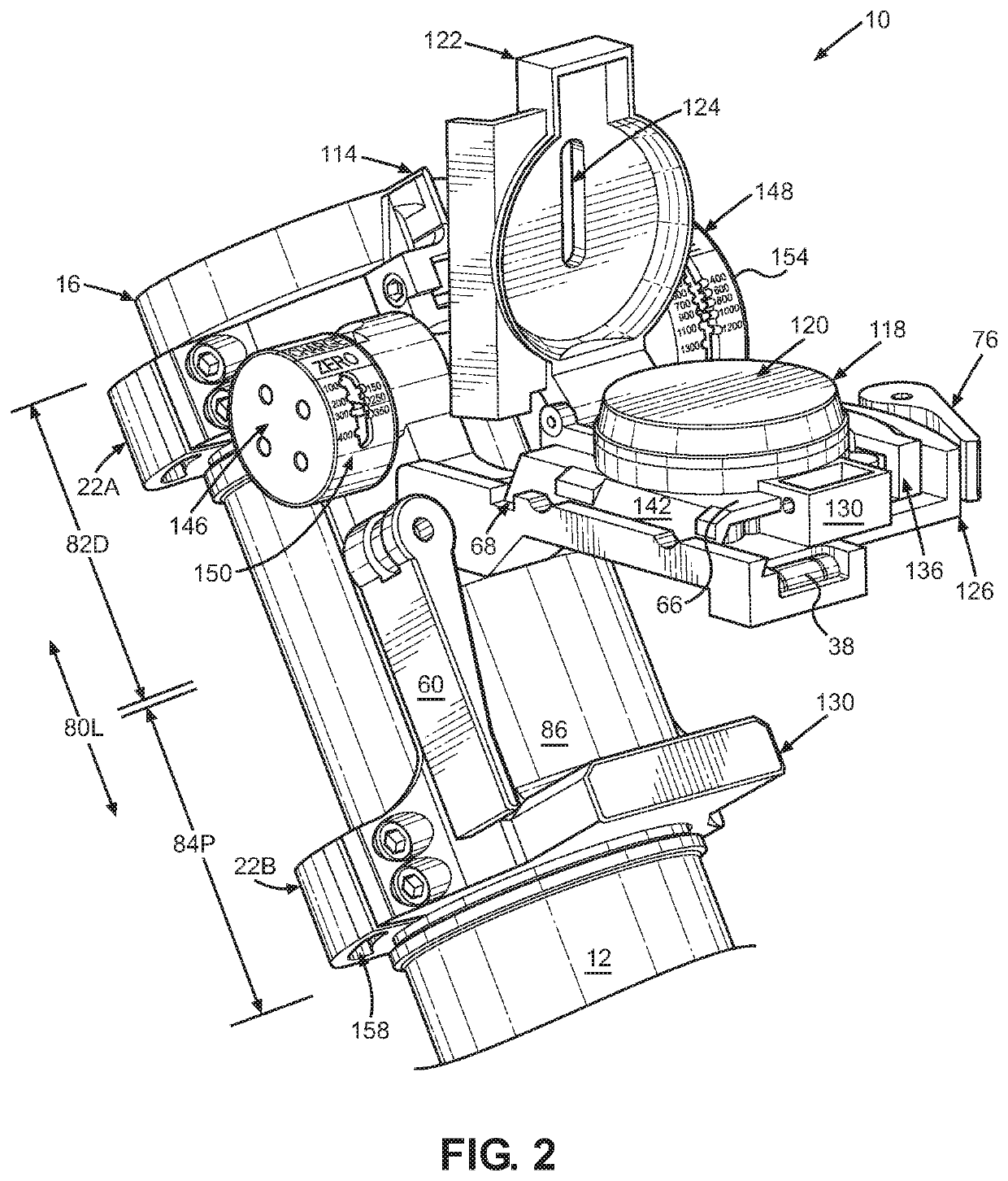
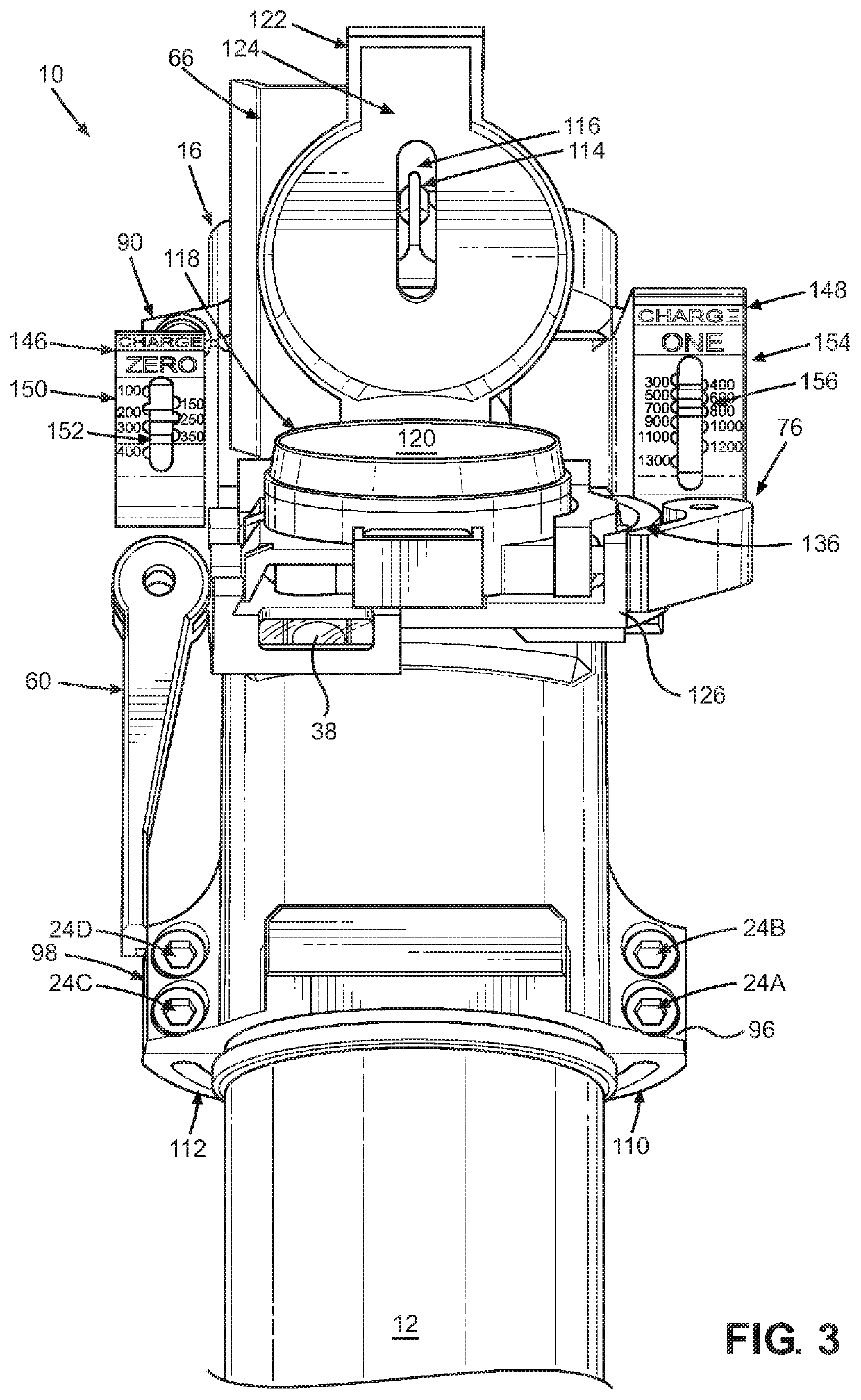
Sighting device for handheld mortar system

Active Publication Date: 2020-03-19
HARTMAN STEVEN T +1
View PDF6 Cites 2 Cited by
  • Summary
  • Abstract
  • Description
  • Claims
  • Application Information

AI Technical Summary

Benefits of technology

The patent describes a new sighting device for a mortar gun that allows faster and more accurate targeting and firing. The device includes a compass, a sight picture, and a distance and charge scale indicator dials, which provide a visual indication of distance and charge without needing to look down and take the eyes off the target. The device also has bright luminescent indicia, pointers, and a front sight blade to help in low-light settings. The bracket mounted sight and its components make it easy to quickly centering and aiming the mortar. Overall, the sighting device offers quicker and more accurate targeting and firing, reducing the need for either exposed light sources or expensive electronic systems.

Problems solved by technology

This is time consuming and requires a mortarman to perform accurate trigonometric calculations before firing when time is of the essence.

Method used


Image

  • Sighting device for handheld mortar system
  • Sighting device for handheld mortar system
  • Sighting device for handheld mortar system

Examples


Embodiment Construction

[0043]Embodiments of the claimed invention will be best understood by reference to the accompanying drawings, which are not necessarily to scale, and wherein like reference numbers indicate identical or functionally similar elements. For purposes of clarity, the spaces between the components are not to scale but enlarged to better illustrate the operation of the device. It will be readily understood that the components of the present invention, as generally described and illustrated in the figures herein, could be arranged and designed in a wide variety of different configurations. The claimed invention may be embodied in many different forms and should not be limited to the illustrated embodiments disclosed. Rather, these embodiments are provided so that this disclosure will be thorough and complete, and will fully convey the scope of the claimed invention to those skilled in the art. Thus, the following more detailed description, as represented in the figures, is not intended to l...


PUM


Abstract

A sighting assembly for a mortar employed in handheld mode. The sighting assembly is attached to the discharge end of a mortar tube by a mounting collar. The collar includes first and second distance indicator dials that employ a pointer to indicate the distance a mortar projectile will travel at different mortar angles and charges. The sighting assembly further includes structure allowing a compass to be locked in a housing by a first cam lever. The entire housing pivots about a cam bolt attached to a second cam lever that can lock the housing in a position parallel to the ground at any angle the mortar is positioned. This will allow a measurement of azimuth to a target to be taken. The azimuth and distance measurements can be used to deliver a mortar projectile to the target while keeping the target in the mortarman's line of sight.

Description

CROSS-REFERENCE TO RELATED PATENT APPLICATIONS[0001]NONESTATEMENT REGARDING FEDERALLY SPONSORED RESEARCH OR DEVELOPMENT[0002]NONEBACKGROUND OF THE INVENTIONField of Invention[0003]The present disclosure generally relates to sighting assemblies for military mortar systems. More particularly, the present invention is a field sighting device removably attachable to handheld battlefield mortars.Description of Related Art[0004]Indirect fire weaponry plays a critical role in modern warfare. Military history has repeatedly demonstrated the effectiveness of indirect fire artillery systems such as mortars: their rapid, high-angle, plunging fires are invaluable against dug-in enemy troops and targets in defilade. Their ability to launch explosive projectiles in a high, parabolic trajectory with a near vertical descent makes it possible to launch attacks from positions lower than the target of the attack.[0005]Mortars are specialized for mobility, tactical flexibility and short range target en...

Claims


Application Information

Patent Timeline
IPC IPC(8): F41G1/50F41F1/06F41G3/06
CPCF41G3/06F41F1/06F41G1/50
Inventor HARTMAN, STEVEN T.STONEBURNER, PAUL
Owner HARTMAN STEVEN T
Learn More