This helps you quickly interpret patents by identifying the three key elements:
Problems solved by technology
Method used
Benefits of technology
Benefits of technology
[0005]An object of the present invention is to provide an optical analyzer capable of performing analysis excellent in spatial resolution and in invasion depth.
Problems solved by technology
The analysis using this optical analyzer may result in a low signal-to-noise ratio and a low spatial resolution.
This optical analyzer may result in a small invasion depth when measuring a measurement subject with a large elastic scattering.
Method used
Image
Click on the blue label to locate the original text in one second.
Reading with bidirectional positioning of images and text.
Examples
first embodiment
of Optical Analyzer
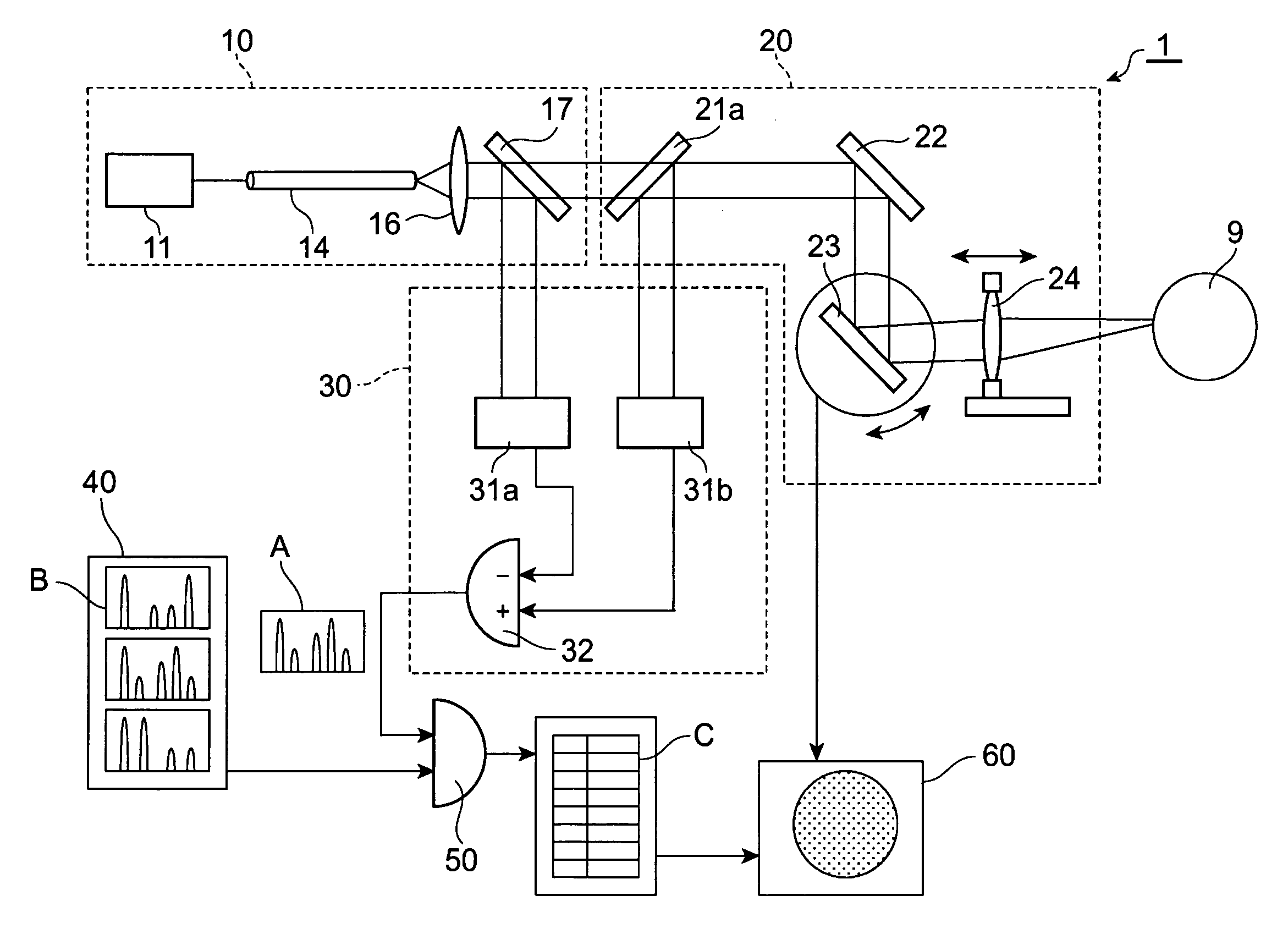
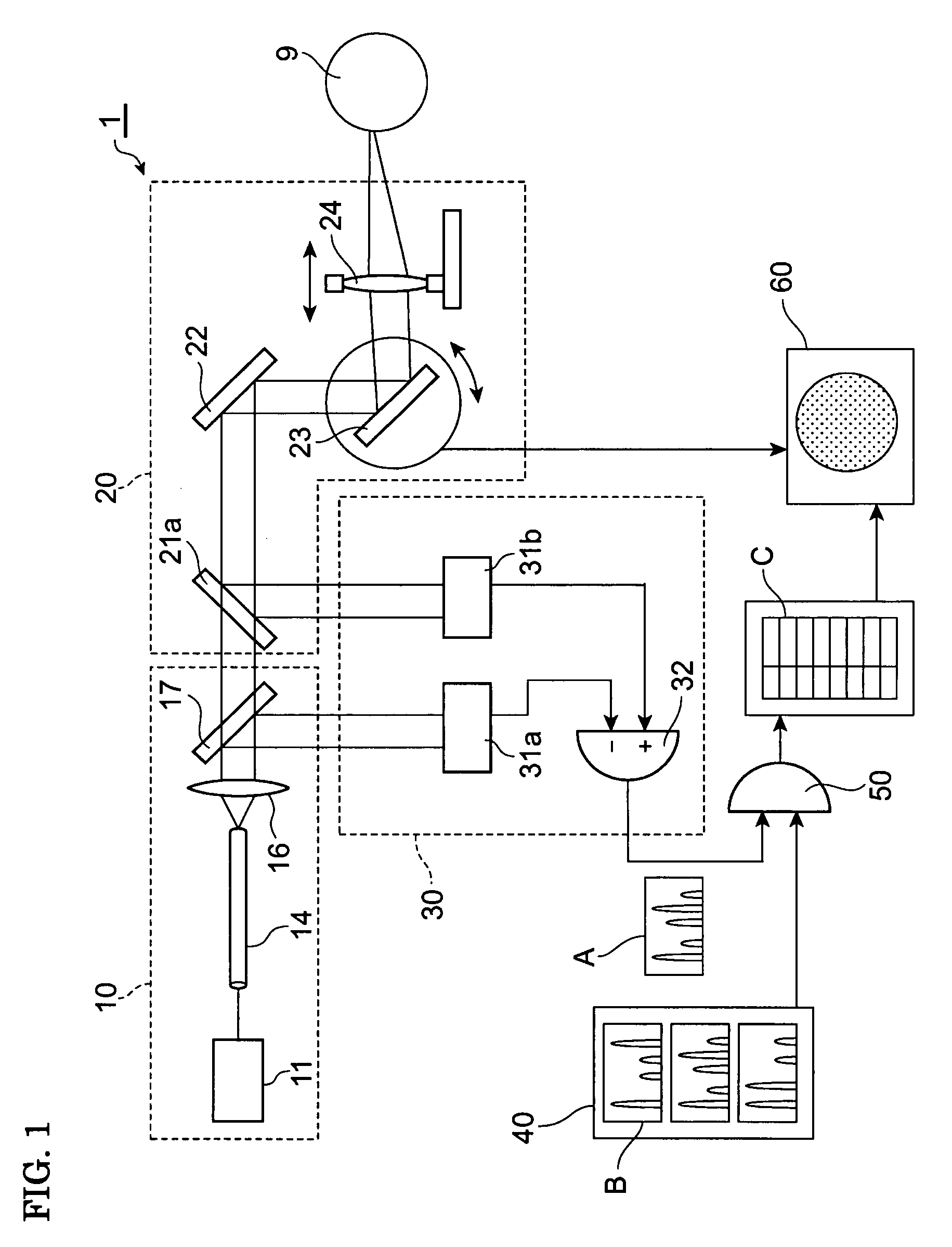
[0023]FIG. 1 is a block diagram showing a first embodiment of an optical analyzer of the present invention. An optical analyzer 1 is a device capable of identifying a measurement subject 9 and evaluating the state of a substance by measuring a loss spectrum. The optical analyzer 1 includes a diagnostic light source section 10, an optical system 20, a spectrum measurement section 30, a storage section 40, an arithmetic section 50, and a display section 60.
[0024]The diagnostic light source section 10 includes a pump pulse source 11, an optical fiber 14, a lens 16, and a semi-transparent mirror 17. A spatial density of an optical power of at least a part of the optical fiber 14 is 1 mW / μm2 or more. The diagnostic light source section 10 outputs diagnostic light having an optical power of 1 μW / nm or more at least in a part of a spectrum bandranging from 0.8 to 3.0 μm.
[0025]The pump pulse source 11 generates pump pulse light having a center wavelength λp within a wave...
second embodiment
of Optical Analyzer
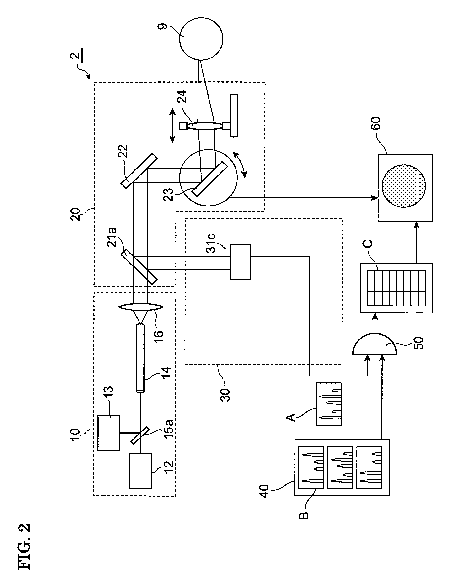
[0034]FIG. 2 is a block diagram showing a second embodiment of the optical analyzer of the present invention. An optical analyzer 2 is a device capable of identifying a measurement subject 9 and evaluating the state of a substance by measuring a Raman scattering spectrum. The optical analyzer 2 includes a diagnostic light source section 10, an optical system 20, a spectrum measurement section 30, a storage section 40, an arithmetic section 50, and a display section 60.
[0035]The diagnostic light source section 10 generates and outputs diagnostic light. The diagnostic light source section 10 includes a seed pulse source 12, a pump source 13, an optical fiber 14, a semi-transparent mirror 15a, and a lens 16. The seed pulse source 12 generates seed pulse light having a center wavelength λs within a wavelength range from 1400 to 1800 nm (more preferably, a wavelength range from 1580 to 1650 nm). The pump source 13 generates pump light having a center wavelength λp in a...
third embodiment
of Optical Analyzer
[0044]FIG. 3 is a block diagram showing a third embodiment of the optical analyzer of the present invention. An optical analyzer 3 is a device capable of identifying a measurement subject 9 and evaluating the state of a substance by measuring a loss spectrum and a Raman scattering spectrum. The optical analyzer 2 includes a diagnostic light source section 10, an optical system 20, a spectrum measurement section 30, a storage section 40, an arithmetic section 50, and a display section 60.
[0045]The diagnostic light source section 10 generates and outputs first diagnostic light and second diagnostic light. The diagnostic light source section 10 includes a pump pulse source 11, a seed pulse source 12, a pump source 13, an optical fiber 14, semi-transparent mirrors 15a and 15b, a lens 16, and a semi-transparent mirror 17. In these elements, the pump pulse source 11 is similar to that of the first embodiment, and the seed pulse source 12 and the pump source 13 are simil...
PUM
Abstract
An optical analyzer performing analysis excellent in spatial resolution and in invasion depth is provided. The analyzer includes a diagnostic light source section including a seed light source which outputs seed light, and a silica optical fiber to which seed light is input and which generates diagnostic light having a HE11 mode field pattern utilizing a nonlinear optical phenomenon, an irradiation optical system converging the diagnostic light and irradiating a measurement subject with the diagnostic light, an acquisition optical system acquiring object light generated at the measurement subject, a spectrum measurement section receiving the object light and measuring a frequency spectrum of the object light, a storage section storing information of a frequency spectrum of a known substance, and an arithmetic section calculating a correspondence between the frequency spectrum of the object light and the frequency spectrum of the known substance, and analyzing the measurement subject based on the calculation result.
Description
TECHNICAL FIELD[0001]The present invention relates to an optical analyzer capable of identifying a measurement subject and evaluating the state of a substance by measuring an optical spectrum, and of being preferably used for sorting medicine and for examining living tissue.BACKGROUND ART[0002]Examples of known optical analyzers capable of identifying measurement subjects and evaluating the states of substances are disclosed in Patent Documents 1 and 2. The optical analyzer disclosed in Patent Document 1 irradiates tissue with near-infraredradiation, measures an absorption spectrum, and determines the kind of fat in adipose tissue in accordance with the absorption spectrum, so as to measure the characteristic of the tissue and classify the tissue. The analysis using this optical analyzer may result in a low signal-to-noise ratio and a low spatial resolution. The optical analyzer disclosed in Patent Document 2 irradiates a measurement subject with pulse light with a wavelength of 1....
Claims
Application Information
Patent Timeline
Application Date:The date an application was filed.
Publication Date:The date a patent or application was officially published.
First Publication Date:The earliest publication date of a patent with the same application number.
Issue Date:Publication date of the patent grant document.
PCT Entry Date:The Entry date of PCT National Phase.
Estimated Expiry Date:The statutory expiry date of a patent right according to the Patent Law, and it is the longest term of protection that the patent right can achieve without the termination of the patent right due to other reasons(Term extension factor has been taken into account ).
Invalid Date:Actual expiry date is based on effective date or publication date of legal transaction data of invalid patent.

