Power seat slide apparatus

a technology of power seat and slide, which is applied in the direction of machine supports, transportation and packaging, and other domestic objects, etc., can solve the problems of large design change and increase of manufacturing costs

Inactive Publication Date: 2009-09-24
AISIN SEIKI KK
View PDF6 Cites 25 Cited by
  • Summary
  • Abstract
  • Description
  • Claims
  • Application Information

AI Technical Summary

Benefits of technology

[0006]In light of the foregoing the present invention provides a power seat slide apparatus, which includes a lower rail adapted to be provided at a vehicle floor, an upper rail slidably supported by the lower rail for retaining a vehicle seat, the upper rail having a pair of walls formed on right and left sides thereof, a lead screw member rotatably supported by the upper rail and extending in a sliding direction of the upper rail, a lead screw nut member provided at the lower rail and threadedly engaged with the lead screw member (for rotatably moving thereon in an axial direction), an output rotation member provided at the upper rail and rotationally connected to the lead screw member, a gearbox rotatably supporting the output rotation member, a drive unit transmitting a rotational drive force to the lead screw member via the output rotation member supported by the gearbox, and a pair of cut-and-bent-away portions, each cut-and-bent-away portion being formed on each of the walls of the upper rail and being arranged at positions to face the lead screw nut member and to contact the lead screw nut member at stroke ends of the upper rail in a front-rear direction thereof.

Problems solved by technology

Notwithstanding, according to the construction of the power seat slide apparatus disclosed in JPH6-19396Y2, because stoppers are required to be provided at the front and rear portions of the screw shaft, respectively, in order to restrict the moving distance of the seat, drawbacks arise that manufacturing cost is increased and a large degree of design change is required when a distance (referred as stroke) between the stopper is needed to be changed.

Method used


Image

  • Power seat slide apparatus
  • Power seat slide apparatus
  • Power seat slide apparatus

Examples


Embodiment Construction

[0017]Embodiments of the present invention will be explained with reference to illustrations of drawing figures as follows.

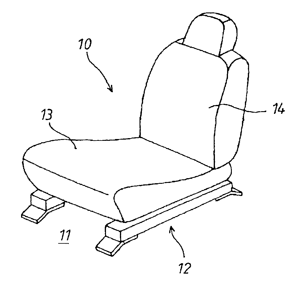
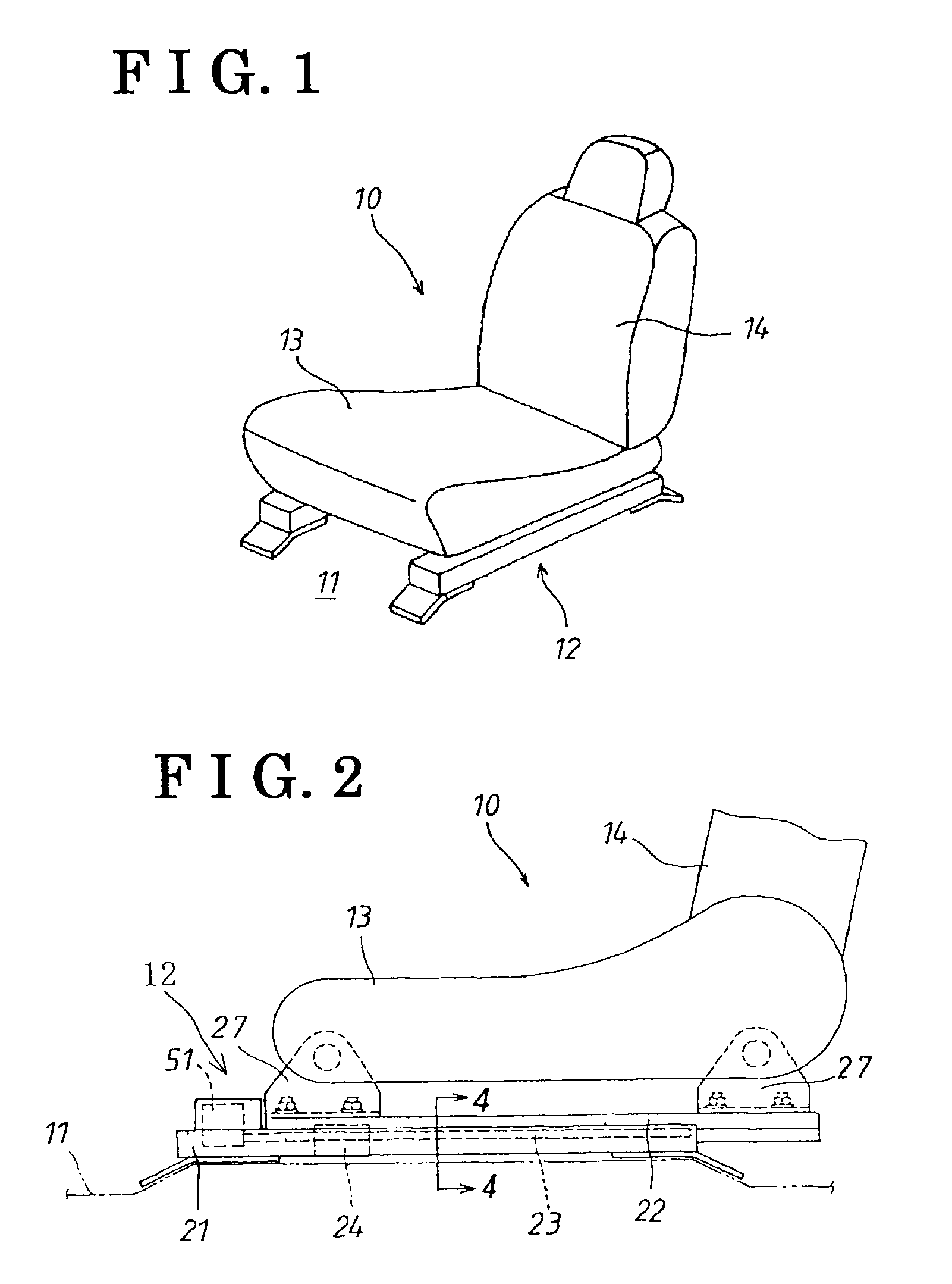
[0018]According to the embodiments of the present invention, directions, such as right, left, front, rear, upward and downward, or the like, correspond to orientations of an occupant seating on a seat for a vehicle. As shown in FIG. 1, a seat 10 for a vehicle is mounted on a vehicle floor 11. The seat 10 for the vehicle includes a power seat slide apparatus 12. The seat 10 for the vehicle includes a seat cushion 13 forming a seat surface and a seatback 14 forming a seatback surface. The seatback 14 is attached to a rear portion of the seat cushion 13 to be rotatable relative to the seat cushion 13 in a front-rear direction of the vehicle and to be fixedly retained at predetermined adjustable angular positions.

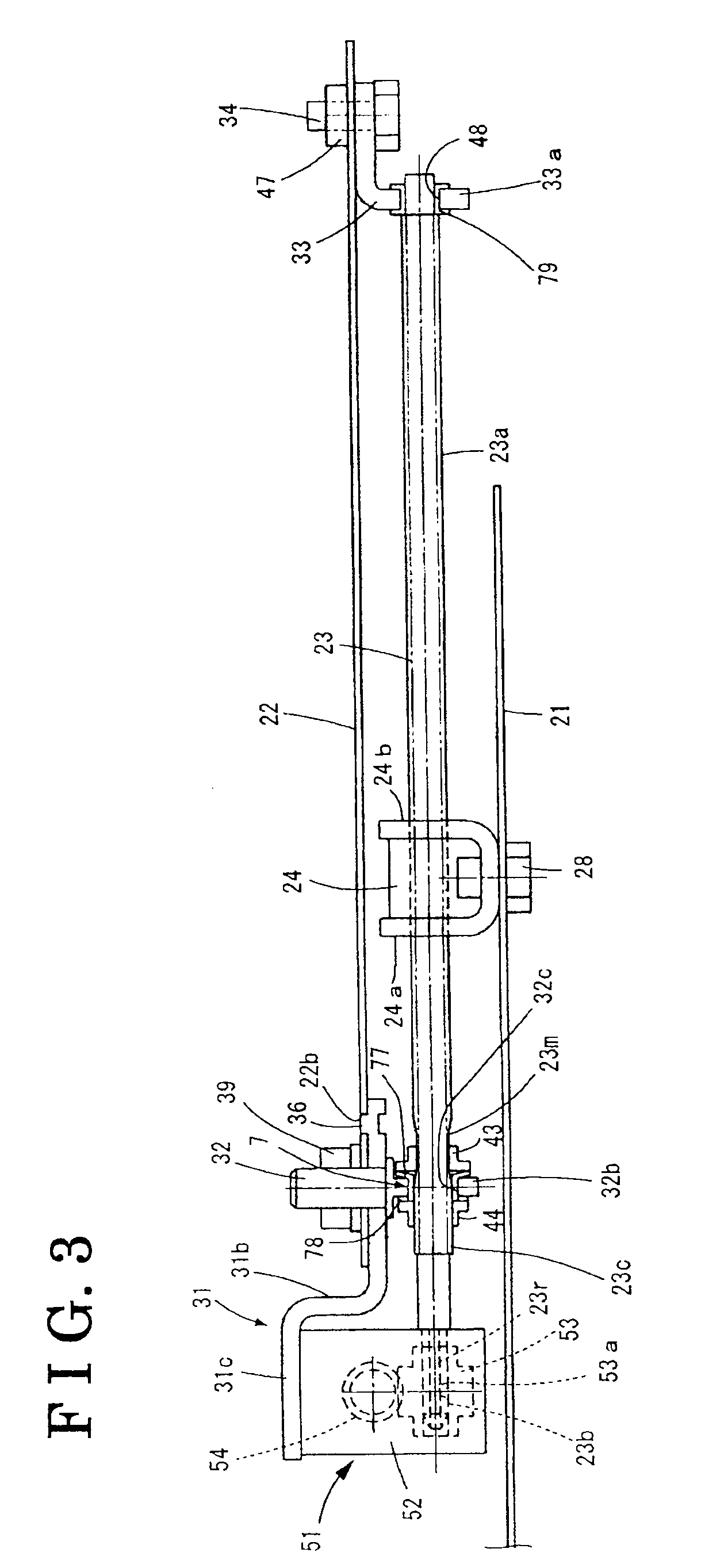
[0019]As shown in FIGS. 2 and 5, the power seat slide apparatus 12 includes a lower rail 21, an upper rail 22, a lead screw member 23, a lead screw nut mem...


PUM


Abstract

A power seat slide apparatus includes a lower rail, an upper rail supported by the lower rail and having a pair of walls, a lead screw member rotatably supported by the upper rail, a lead screw nut member provided at the lower rail and threadedly engaged with the lead screw member, an output rotation member provided at the upper rail and connected to the lead screw member, a gearbox rotatably supporting the output rotation member, a drive unit transmitting a rotational drive force to the lead screw member via the output rotation member, and a pair of cut-and-bent-away portions, each cut-and-bent-away portion being formed on each of the walls of the upper rail and being arranged at positions to face the lead screw nut member and to contact the lead screw nut member at stroke ends of the upper rail in a front-rear direction thereof.

Description

CROSS REFERENCE TO RELATED APPLICATIONS[0001]This application is based on and claims priority under 35 U.S.C. § 119 to Japanese Patent Application No. 2008-076242, filed on Mar. 24, 2008, the entire contents of which is incorporated herein by reference.FIELD OF THE INVENTION[0002]The present invention relates to a power seat slide apparatus applied to a seat for a vehicle.BACKGROUND[0003]A known power seat slide apparatus, which slides an upper rail relative to a lower rail in a longitudinal direction of a vehicle by rotating a screw shaft by means of a rotation of a motor, is disclosed in JPH6-19396Y2. According to the power seat slide apparatus disclosed in JPH6-19396Y2, a stopper is provided at each of front and rear portions of the screw shaft, and a moving distance of the upper rail, that is, a moving distance of the seat in a longitudinal direction thereof is restricted by contacting the stopper and a reduction gear portion.[0004]Notwithstanding, according to the construction ...

Claims


Application Information

Patent Timeline
Patent Type & Authority Applications(United States)
IPC IPC(8): F16M13/00
CPCB60N2/067B60N2/0727B60N2/0705
Inventor KOGA, YOSHITAKASHIMIZU, JUERU
Owner AISIN SEIKI KK
Why Eureka
Try Eureka