

Articulating faucet and joint therefor
- Summary
- Abstract
- Description
- Claims
- Application Information
AI Technical Summary
Benefits of technology
Problems solved by technology
Method used
Image

Examples
Embodiment Construction
)
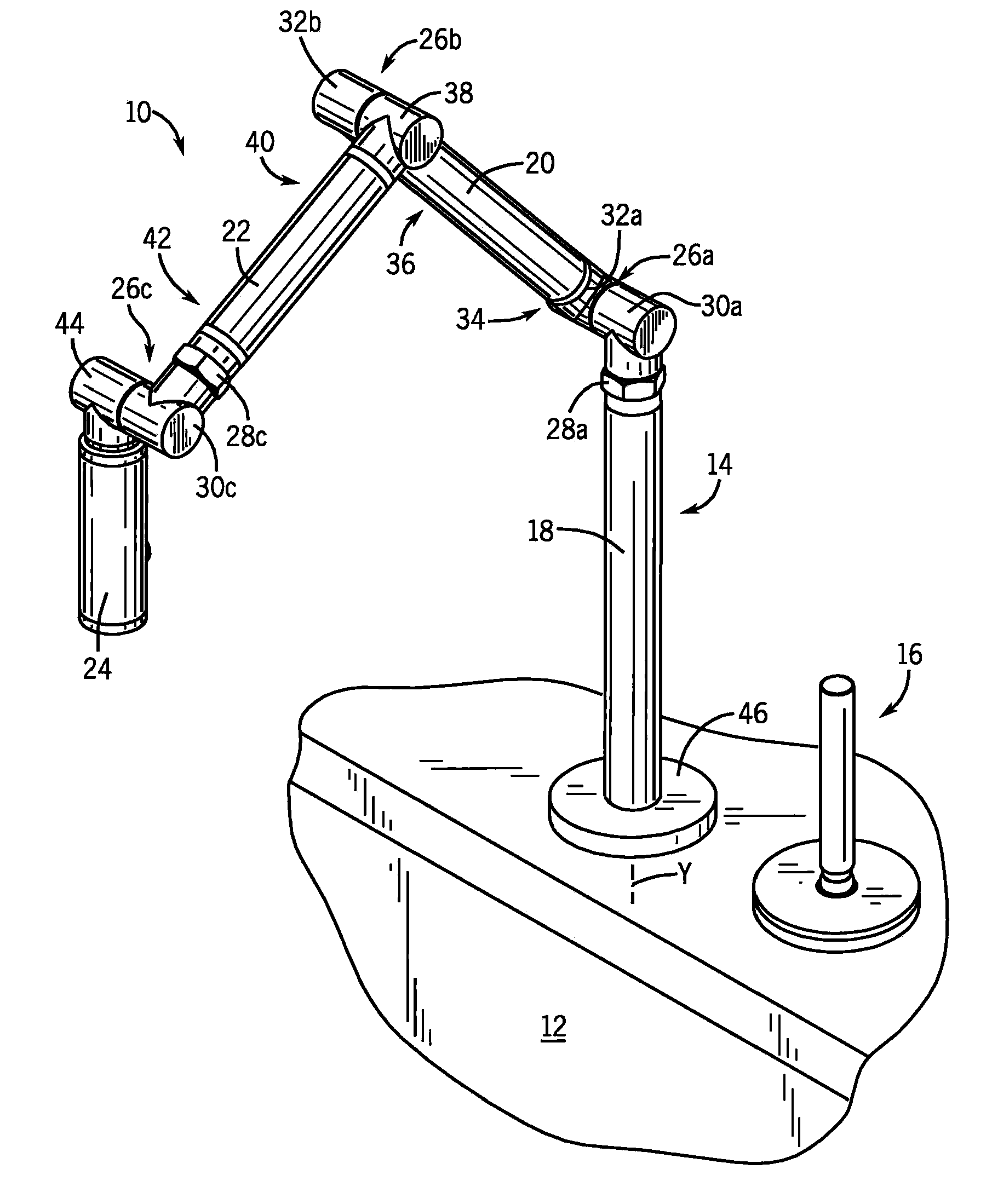
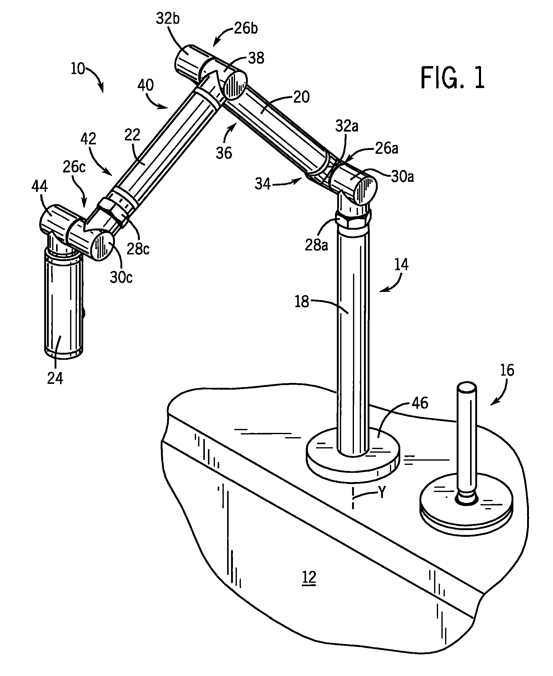
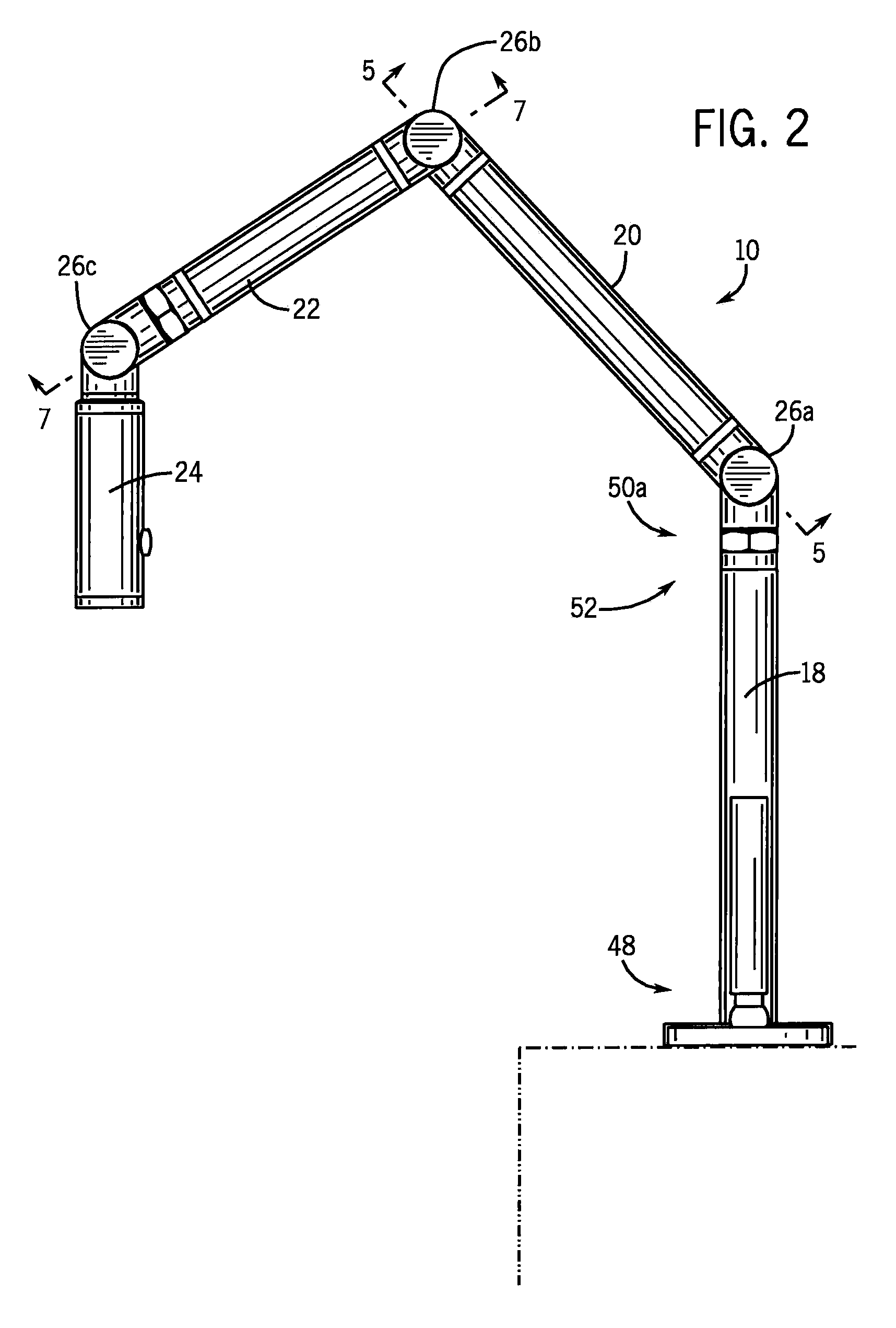
[0021]FIGS. 1-3 illustrate an articulating faucet 10 suitable for use with a sink, lavatory, utility basin or other plumbing vessel, particularly those having a large basin, (e.g., a kitchen sink or other plumbing basin), such as basin 12. A tubular, segmented spout assembly 14 and a moveable faucet handle 16 can be mounted to either a mounting deck of the basin 12 or to a surrounding support surface (e.g., countertop, etc.). The spout assembly 14 includes a vertical support 18, two moveable swing arms 20, 22 and a spray head assembly 24. The spout assembly 14 further includes a number of joints 26A-C that enable pivoting of the swing arms 20, 22 and spray head assembly 24. Joints 26A and 26C each permit rotation about two axes, which lie in and provide movement in separate perpendicular planes. Joint 26B permits rotation around one axis. It should be noted that the distal joint 26C (adjacent the spray head assembly 24) is a floating joint in that its position in space can be shift...
PUM
 Abstract
Description
Claims
Application Information