Bracket assembly for lifting and supporting a foundation

Inactive Publication Date: 2005-09-29
DIXIE ELECTRICAL MFG
View PDF30 Cites 8 Cited by
  • Summary
  • Abstract
  • Description
  • Claims
  • Application Information

AI Technical Summary

Benefits of technology

[0007] Accordingly, the present invention improves existing brackets so that the bracket accommodates stabilization and lifting piers of various sizes ranging from about one inch to about four inches in diameter and various shapes such as round, square, and polygonal. Simultaneously, the present invention provides engagement to limit rotation or shifting of the bracket with respect to an installed pier. A removable gate, or pin, feature allows the contractor to install the bracket upon the foundation either before or after placement of a pier. The present invention also allows a contractor to use multiple systems for placement of a pier such as rotational torque drive and direct resistance drive among others. The present invention maintains placement and orientation of a pier to resist rotation and slippage. Further, the present invention permits locating installation tools and components over the center of the piers to reduce induced bending moment at the junction of a pier and a bracket, particularly where the foundation rest thereon.
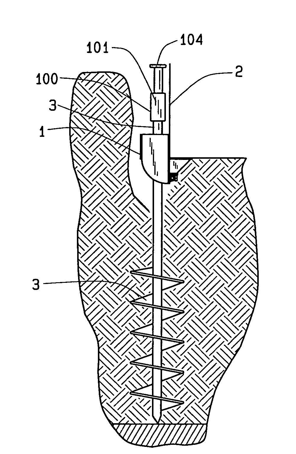
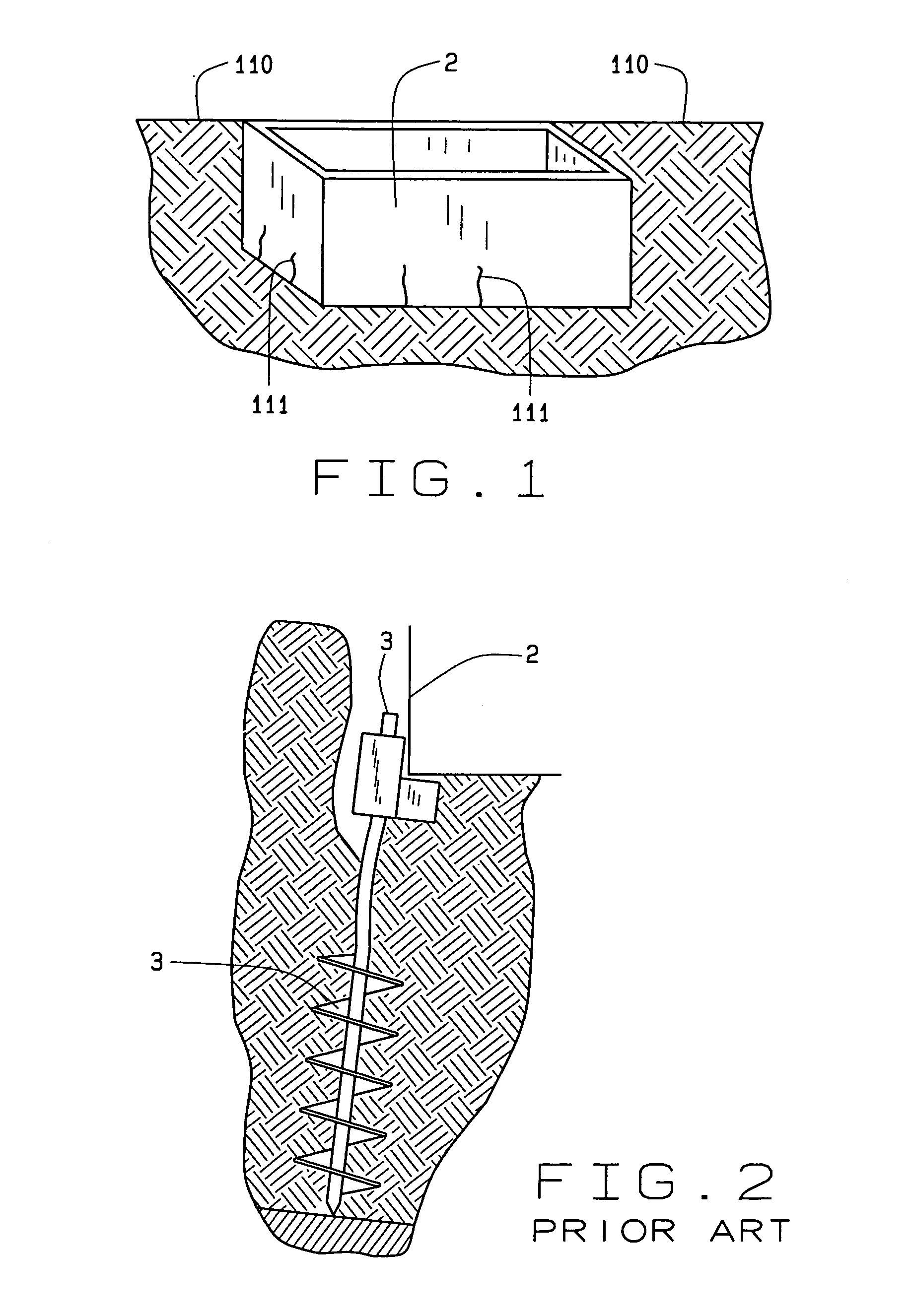
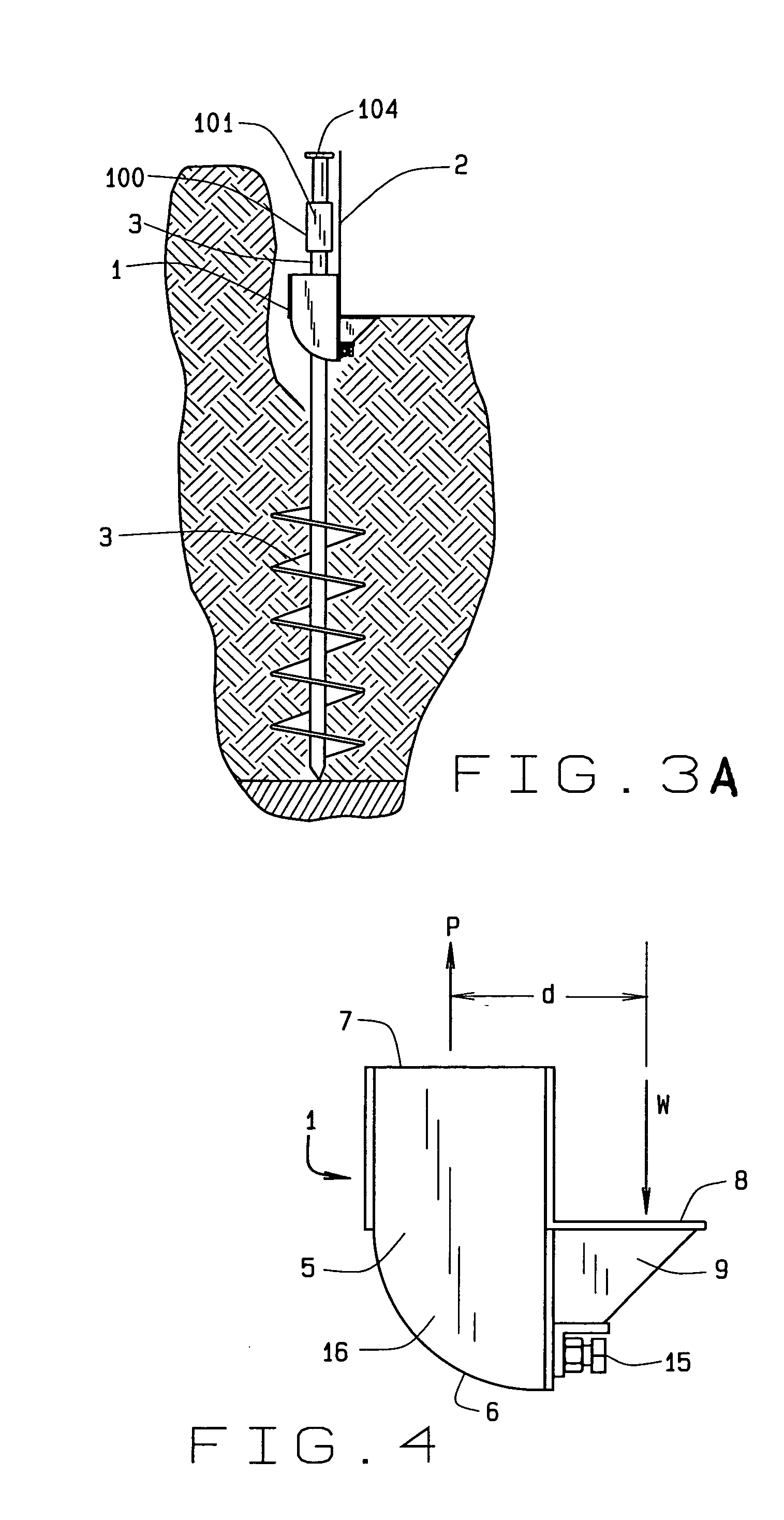
[0009] In the present invention, the structural bearing angle member supports and lifts the foundation relative to the pier kept between two parallel plates. The pier guide provides a moveable stop on the front edge of the pier nearest the foundation. In addition, the pier guide also provides a pin to engage the rear edge of the pier to prevent the pier from shifting out of the bracket. Alternatively, the pier guide has a gate with a moveable plate or a tube shape. The moveable stop eliminates any gap, front to back, between the front edge of an installed pier and the lower portion of the bracket assembly.
[0011] It is a further object of the present invention to prevent shifting and rotation of the bracket with respect to a pier particularly when subjected to the weight of the foundation.
[0012] It is a still further object of the present invention to eliminate movement of a bracket away from a foundation.
[0013] It is an even still further object of the present invention to prevent disengagement of a bracket from the bottom of a foundation.

Problems solved by technology

Piers directly below a foundation become impractical because of overhead height constraints and damage to an existing structure.
Short piers have proven cumbersome and time consuming for contractors and result in a pier of questionable flexural rigidity.
The difficulty in providing a bracket assembly is shown by prior art bracket designs that transferred a foundation load to a particular style of pier.
Rotation causes the foundation support portion of a bracket to disengage from a foundation opening a gap, thus reducing the effective load capacity of a bracket.

Method used


Image

  • Bracket assembly for lifting and supporting a foundation
  • Bracket assembly for lifting and supporting a foundation
  • Bracket assembly for lifting and supporting a foundation

Examples


second embodiment

[0046] the bracket assembly 1 appears in FIG. 8. The bracket assembly 1 begins with a hollow tube 25, generally square in cross section and oriented upright. Serving as a pier guide, the tube 25 fits the shape of the top of a pier 3. Those skilled in the art will recognize that a variety of shapes can be used in addition to the square shape of the tube 25 described. A bearing angle 8 spans across the tube 25 in an L shape cross section with the vertex of the L shape generally at the center of the present invention 1. The bearing angle 8 contacts the front of the tube 25. Centered beneath the bearing angle 8, a gusset 9 hangs downwards and joins to the front of the tube 25 as well. The gusset 9 has a planar shape generally triangular and perpendicular to a leg of the bearing angle 8 and to the tube 25. Beneath the gusset 9, an angle 10 spans the width of the tube 25. As before, the gusset 9 welds or joins to the bearing angle 8, the lower plate 18, and the angle 10. The angle 10 has ...

third embodiment

[0051] the bracket assembly 1 appears in FIG. 11. The bracket assembly 1 begins with two parallel and spaced apart plates 16. A plate 16 has a generally rectangular shape with two ends. The first end 6 has a quarter circle or arcuate shape when viewed from the side of the bracket assembly 1 and the opposite second end 7 has a horizontal or square shape denoting the top of the bracket assembly 1. A bearing angle 8 spans across the plates 16 in an L shaped cross section with the vertex of the L shape generally at the center of the present invention. Centered beneath the bearing angle 8, a gusset 9 depends to a lower plate 18. The gusset 9 has a planar shape generally triangular and parallel to the plates 16. The lower plate 18 spans between the plates 16 beneath the bearing angle 8 to the first ends 6. Beneath the gusset 9, an angle 10 spans across the lower plate 18. The gusset 9 joins by welding to the bearing angle 8, the lower plate 18, and the angle 10. The angle 10 has a general...

fourth embodiment

[0058] the bracket assembly 1 appears in FIG. 15. The bracket assembly 1 begins with two parallel and spaced apart plates 16 as in FIG. 5. A plate 16 has a generally rectangular shape with two ends. The first end 6 has a quarter circle or arcuate shape when viewed from the side of the bracket assembly 1 and the opposite second end 7 has a horizontal or square shape denoting the top of the bracket assembly 1. A bearing angle 8 spans across the plates 16 in an L shaped cross section with the vertex of the L shape generally at the center of the present invention 1. Centered beneath the bearing angle 8, a gusset 9 depends to a lower plate 18. The gusset 9 has a planar shape generally triangular and parallel to the plates 16. The lower plate 18 spans between the plates 16 beneath the bearing angle 8 to the first ends 6. Beneath the gusset 9, a angle 10 spans the lower plate 18. The angle 10 has a generally L shaped cross section with the vertex of the L shape towards the center of the pr...


PUM


Abstract

A bracket assembly rests upon a pier set adjacent to a foundation and a secondary component elevates the bracket assembly. The bracket provides adjustable engagement to limit rotation of the bracket with respect to an installed pier. The bracket assembly has an housing, a bearing member, load transfer plates, reinforcing means, and an adjusting bolt beneath the bearing member. The housing is either two parallel plates or a tube. In the plates embodiment, two slots receive either a pin, a gate alone, or a gate with a moveable plate. In the tube embodiment, the pier fits snugly within the tube. Further, the bracket permits locating tools over the piers to reduce induced bending moment at the junction of the pier and the bracket. The bracket assembly stabilizes and lifts piers.

Description

BACKGROUND OF THE INVENTION [0001] The bracket assembly for lifting and supporting a foundation relates to L shaped foundation brackets in general and more specifically to improvements in the connections of the bracket to a pier for supporting a foundation. A unique aspect of the present bracket assembly is a removable gate and adjustable bolt that position the bracket assembly upon a pier to resist moment, translation, and rotation of a bracket. [0002] The bracket assembly transfers the weight, or load, supported by a foundation, or footing, to a pier, pile or deeper foundation. The bracket assembly commonly cradles a footing, or foundation wall, of a structure, or building, then transfers the load to a pile or pier that bears on bedrock or other load bearing strata beneath the existing foundation. The main concept of this invention is to support a settling foundation Prior art designs have previously supported failed or shallow footings. [0003] Piers made of concrete, reinforced c...

Claims


Application Information

Patent Timeline
IPC IPC(8): E02D5/00E02D11/00E02D27/48E02D35/00E04G23/06
CPCE02D27/48E04G23/06E02D35/00E04G23/065
Inventor FAIRES, GUY L.JACOBS, JAMES E.GARTON, STANLEY C.
Owner DIXIE ELECTRICAL MFG
Why Eureka
Try Eureka