Bracket assembly for lifting and supporting a lightweight foundation

a lightweight foundation and bracket technology, applied in the direction of foundation engineering, bulkheads/piles, construction, etc., can solve the problems of unstable structure supported on a shallow foundation or lightweight structure or foundation element, unstable structure, unstable structure, etc., to achieve easy and safe adjustment, reduce the moment of rotation and translation of weldments

Inactive Publication Date: 2008-01-17
FAIRES GUY L +2
View PDF7 Cites 28 Cited by
  • Summary
  • Abstract
  • Description
  • Claims
  • Application Information

AI Technical Summary

Benefits of technology

[0013] Accordingly, the present invention modifies existing brackets so that the bracket adjusts readily to piles or deep foundation piers of various sizes ranging from about one inch to about two inches in diameter and various shapes such as round, square, and polygonal. The present invention uses a U-shaped bolt to minimize moment, rotation, and translation of a weldment. The U-shaped bolt is easily and safely adjusted to fix the weldment upon a pile or deep foundation pier and position the weldment against a foundation or lightweight structure or foundation element. By fixing the weldment against rotation and translation from the lightweight structure or foundation element, an effective bearing area is maintained between the lightweight structure or foundation element and the weldment. Further, the present invention has a sleeve to guide the pile or deep foundation pier which in cooperation with the U-shaped bolt compensates for misalignment of the pile or deep foundation pier.

Problems solved by technology

A structure supported on a shallow foundation or lightweight structure or foundation element may become unstable and settle as a result of soil conditions or flaws in the original foundation design.
In time, foundation settlement results in a structure becoming out of level and eventually structural damage.
Without a stable foundation to rest upon, a structure will become unsafe and require additional foundation reinforcement to stabilize the structure.
However, placement of these piles or deep foundation piers beneath an existing structure, foundation or lightweight structure or foundation element can be difficult, often requiring deep excavations to provide the needed clearances.
Piles or deep foundation piers directly below a lightweight structure or foundation element become impractical because of excavation costs and narrow clearances between lightweight structure or foundation elements and adjacent structures.
Short piles or deep foundation piers have proven cumbersome and time consuming for contractors and result in a pile or deep foundation pier of questionable flexural rigidity.
The rotation reduces the effective bearing area between the bracket and the lightweight structure or foundation element.
The difficulty in providing a bracket assembly is shown by prior art bracket designs that transferred a foundation load to a particular style of pile or deep foundation pier.
Rotation causes the foundation support portion of a bracket to disengage from a foundation opening a gap, thus reducing the effective load capacity of a bracket.
However, the location and orientation of the lower bracket adjustment bolt requires contractors to reach under the foundation to adjust the bracket, possibly causing an unsafe working condition.
The pipe sleeve provides the fixity required to limit rotation of the bracket but no adjustments are possible upon the pipe sleeve.
The wedge anchors may induce a horizontal load upon the pipe sleeve that could eventually cause failure of the wedge anchors or disengagement of the pipe sleeve from the lightweight structure or foundation element.

Method used


Image

  • Bracket assembly for lifting and supporting a lightweight foundation
  • Bracket assembly for lifting and supporting a lightweight foundation
  • Bracket assembly for lifting and supporting a lightweight foundation

Examples


Embodiment Construction

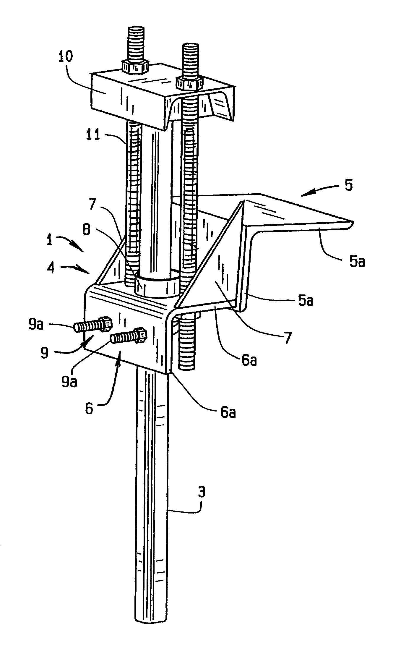
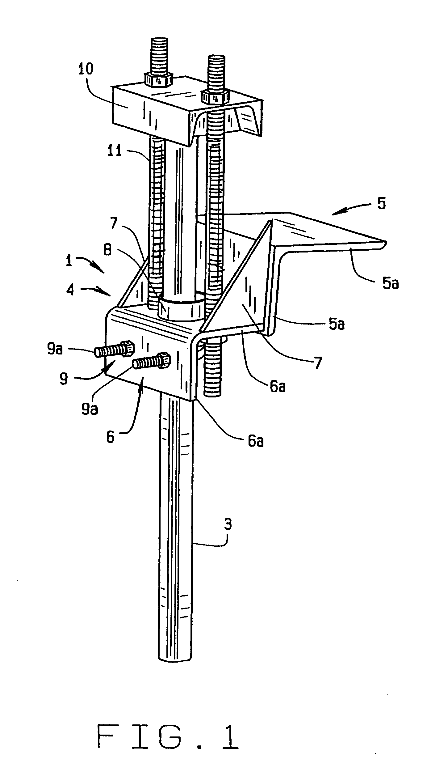
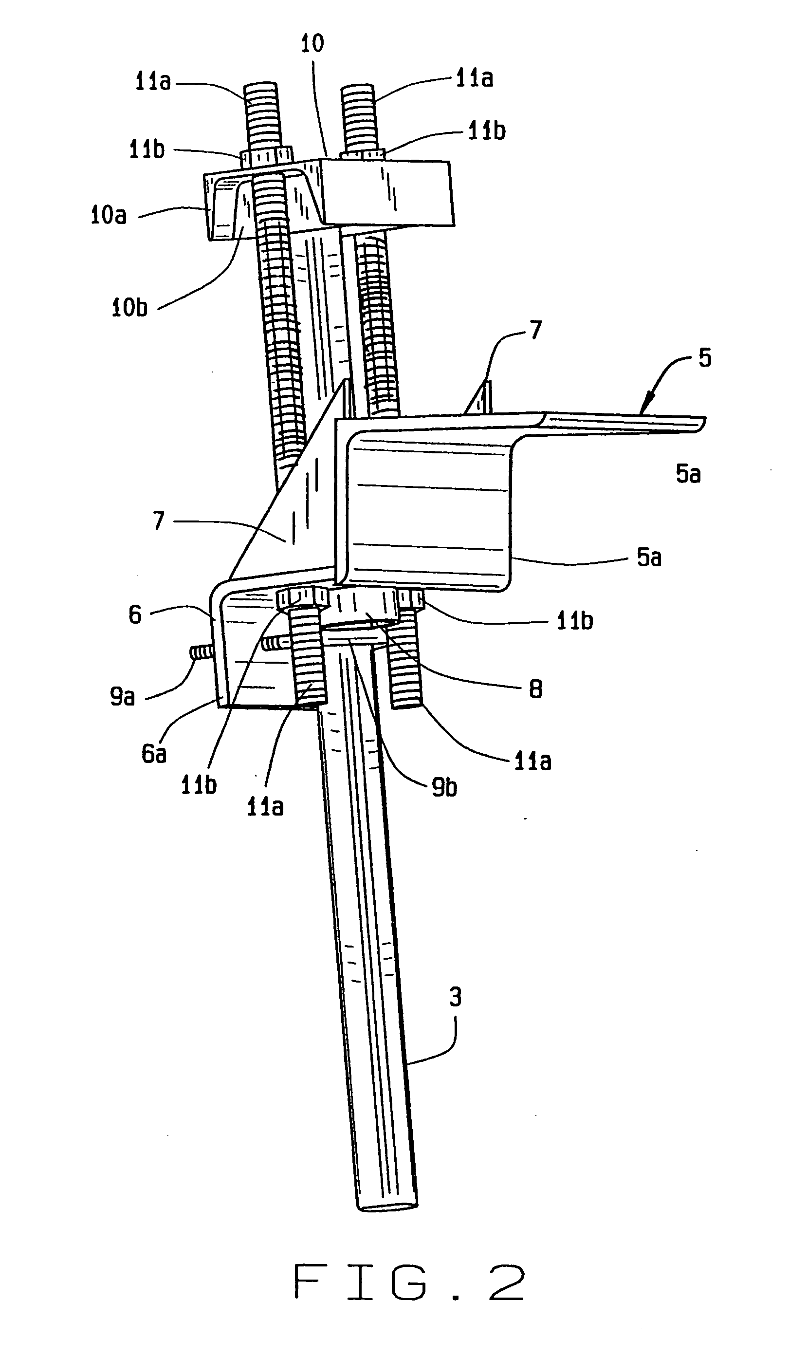
[0038] The present art overcomes the prior art limitations by providing a bracket assembly 1 that lifts and supports a lightweight structure or foundation element 2 with adjustable lifting and pile or deep foundation pier positioning hardware, that transfers lightweight structure or foundation element loads to piles or deep foundation piers 3 of various shapes and sizes, and that does not induce rotation of the bracket upon a pile or deep foundation pier. The present invention is installed upon a pile or deep foundation pier 3 adjacent to a foundation or lightweight structure or foundation element 2, and has limited rotation upon the pile or deep foundation pier due to the securing action of a U-shaped bolt 9. The U-shaped bolt 9 is oriented with threadably adjustable nuts upon stems facing away from the foundation 2 thus allowing an installer to make adjustments to the present invention safely without reaching beneath a supported structure or lightweight structure or foundation ele...


PUM


Abstract

A bracket assembly rests upon a pile or deep foundation pier set adjacent to a lightweight structure or foundation element such as a porch. The bracket slides upon a pile or deep foundation pier and adjusts from the side of the pile or deep foundation pier. The bracket assembly has a weldment with bearing and guide members. The bearing member supports the lightweight structure or foundation element while the guide member raises the bearing member on the pile or deep foundation pier. The guide member has a sleeve and U-shaped bolt to grasp the pile or deep foundation pier. A cap plate atop the pile or deep foundation pier connects to the guide member through rods. Turning nuts on the upper end of the rods pulls them and thus the lightweight structure or foundation element upwards. The bracket assembly is lightweight and supports approximately five thousand pounds.

Description

CROSS REFERENCE TO RELATED APPLICATION [0001] This continuation in part patent application claims priority to the non-provisional patent application having Ser. No. 11 / 089,865, which was filed on Mar. 25, 2005.BACKGROUND OF THE INVENTION [0002] The bracket assembly for lifting and supporting a foundation relates to L shaped foundation brackets in general and more specifically to improvements in the connections of the bracket to a pile or deep foundation pile or deep foundation pier for supporting a lightweight structure or foundation element. A unique aspect of the present bracket assembly is an adjustable U-shaped bolt and mechanism that secures the bracket against rotation and translation relative to a pile or deep foundation pile or deep foundation pier. The U-shaped bolt also permits access from the side and a sleeve that allows the assembly to move upon a pile or deep foundation pile or deep foundation pier. [0003] Generally the top of a pile or pier is defined as top and the b...

Claims


Application Information

Patent Timeline
Patent Type & Authority Applications(United States)
IPC IPC(8): E02D5/00
CPCE02D27/16
Inventor FAIRES, GUY L.JACOBS, JAMES E.GARTON, STANLEY C.
Owner FAIRES GUY L
Why Eureka
Try Eureka