Articulated joint mechanism for cable-based and tensegrity structures

a joint mechanism and cable-based technology, applied in the direction of pivotal connections, shafts for rotary movements, constructions, etc., can solve the problems of lateral compressive on the rods, increasing the likelihood of mechanical failure of components, and the structure being inclined to deviate from its intended shape, so as to minimize the moment of the rod or the cable on the joint

Active Publication Date: 2022-10-11
GEORGIA TECH RES CORP
View PDF20 Cites 0 Cited by
  • Summary
  • Abstract
  • Description
  • Claims
  • Application Information

AI Technical Summary

Benefits of technology

[0007]The disadvantages of the prior art are overcome by the present invention which, in one aspect, is a joint for a structure that includes at least one rod and a plurality of cables, each cable having an outside diameter. A rod end is affixable to the rod so that the rod has a rod centerline that passes through the rod end. The rod end includes a mechanism that allows the rod end to pivot about a center point that is on the rod centerline. A cable attachment device is couplable to each of the plurality of cables and is coupled to the rod end. The cable attachment device is configured to hold each of the plurality of cables coupled thereto in a relationship to the rod end so that each of the plurality of cables has a cable centerline that intersects the center point so as to minimize any moments from the rod or the cables on the joint.

Problems solved by technology

Tension in the cables causes lateral compressive on the rods.
In some joints, a-symmetry in the connections can result in moments on the joints which result in the disadvantage of increasing the likelihood of mechanical failure of the components.
Also, such moments can result in the structure being inclined to deviate from its intended shape.

Method used


Image

  • Articulated joint mechanism for cable-based and tensegrity structures
  • Articulated joint mechanism for cable-based and tensegrity structures
  • Articulated joint mechanism for cable-based and tensegrity structures

Examples


Embodiment Construction

[0029]A preferred embodiment of the invention is now described in detail. Referring to the drawings, like numbers indicate like parts throughout the views. Unless otherwise specifically indicated in the disclosure that follows, the drawings are not necessarily drawn to scale. As used in the description herein and throughout the claims, the following terms take the meanings explicitly associated herein, unless the context clearly dictates otherwise: the meaning of “a,”“an,” and “the” includes plural reference, the meaning of “in” includes “in” and “on.”

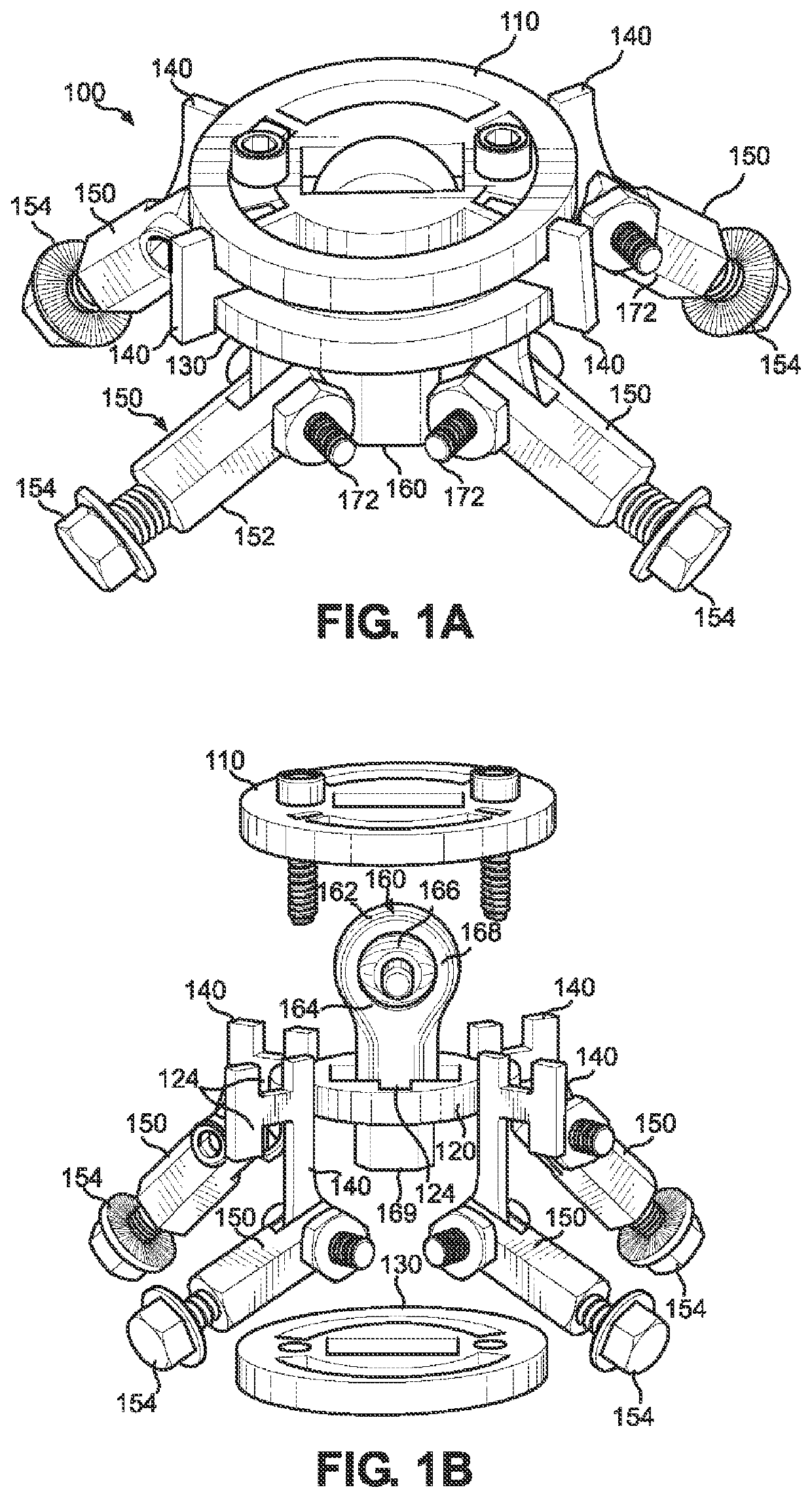
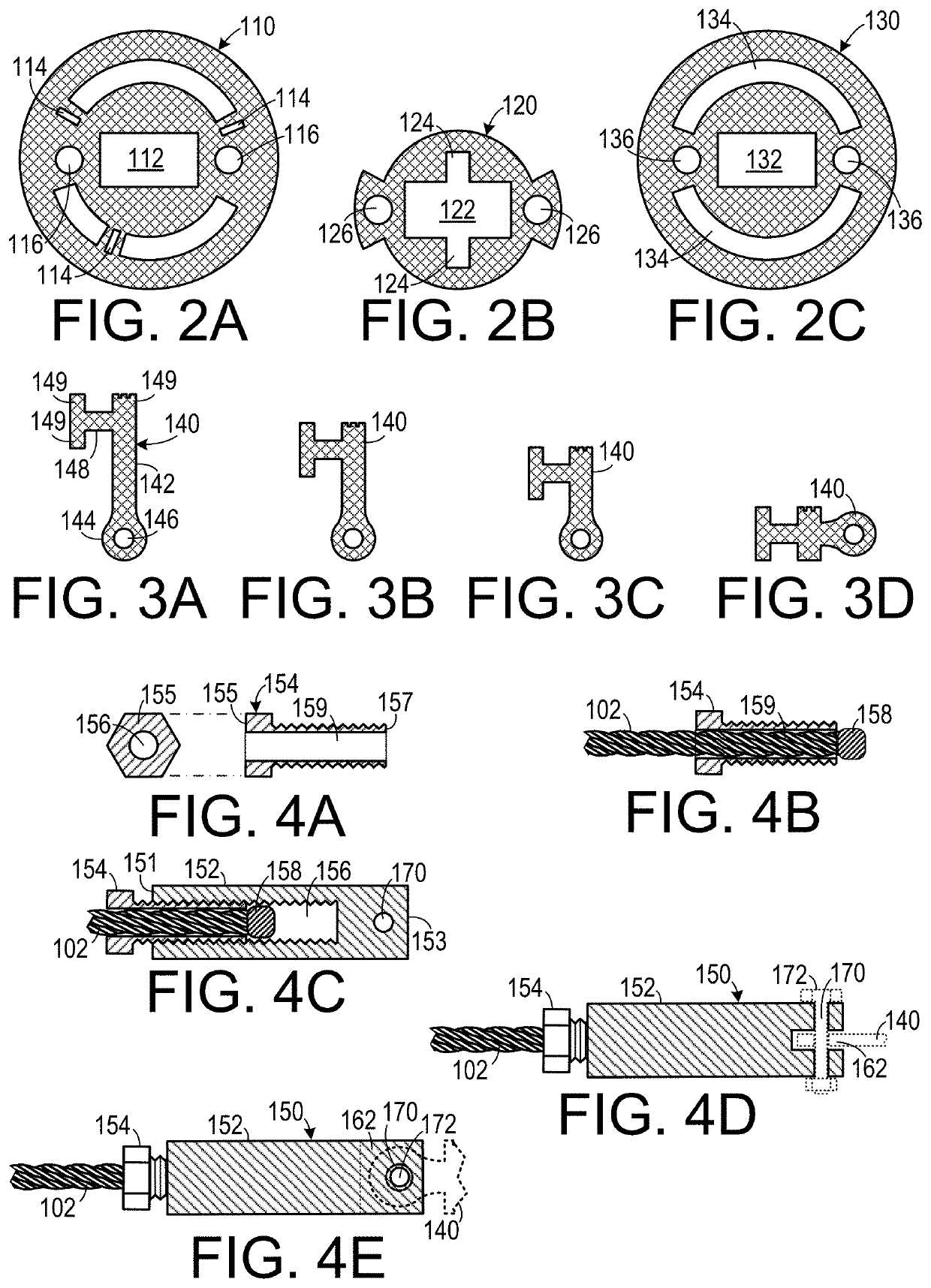
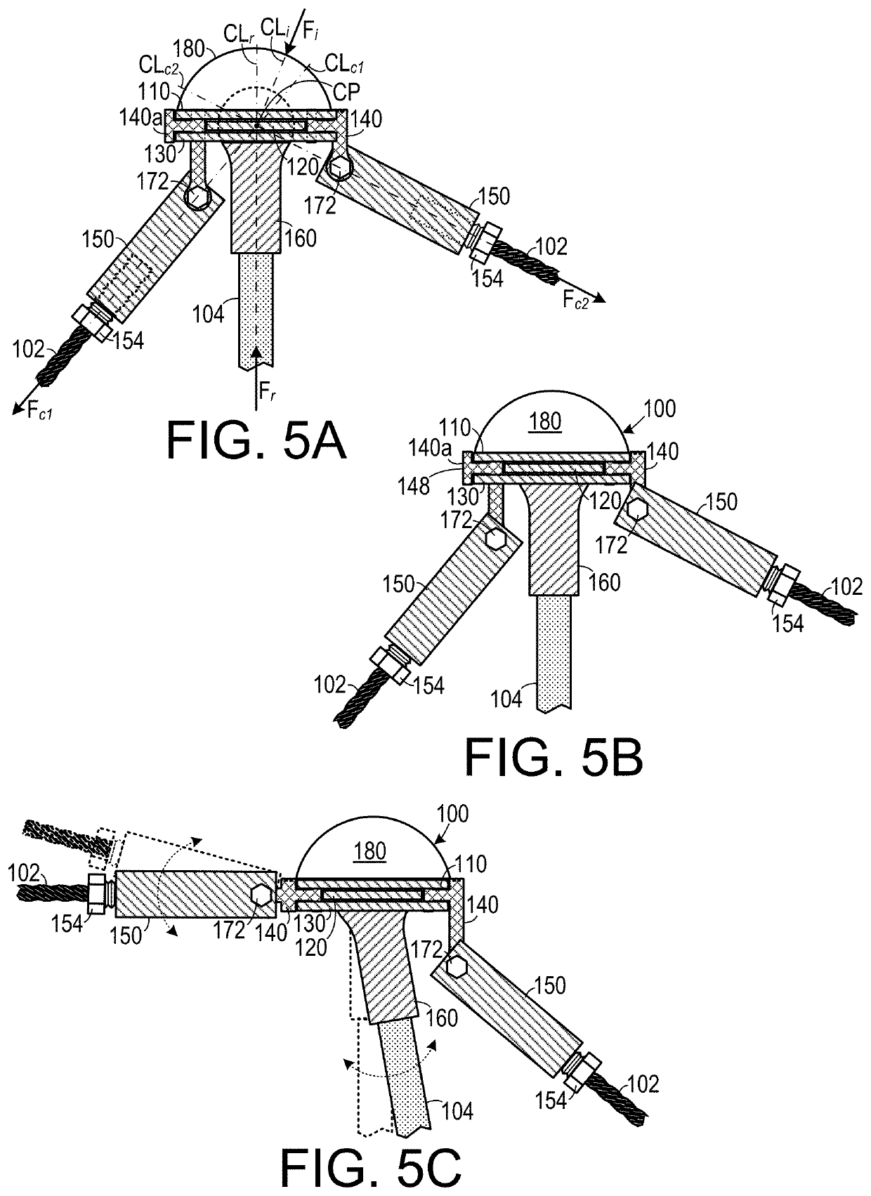
[0030]As shown in FIGS. 1A and 1B, one embodiment of a joint 100 for use in structures that include rods under compression and cables under tension, includes a rod end 160 (for example, one type of rod end is a ball joint rod end available from McMaster-Carr) that is held by a second (center) plate 120 between a first (top) plate 110 and a third (bottom) plate 130. A plurality of wing members 140 are secured by the first plate 110 and ...


PUM


Abstract

In a joint (100) for a structure that includes at least one rod (104) and a plurality of cables (102), each cable (102) having an outside diameter, a rod end (160) is affixable to the rod (104) so that the rod has a rod (104) centerline that passes through the rod end (160). The rod end (160) includes a mechanism (166) that allows the rod end (160) to pivot about a center point that is on the rod centerline. A cable attachment device (150) is couplable to each cable (102) and to the rod end (160). The cable attachment device (150) holds each cable (102) coupled thereto in a relationship to the rod end (160) so that each cable (102) has a cable centerline that intersects the center point so as to minimize any moments from the rod (104) or the cables (102) on the joint (100).

Description

CROSS-REFERENCE TO RELATED APPLICATION(S)[0001]This application claims the benefit of U.S. Provisional Patent Application Ser. No. 62 / 272,409, filed Dec. 29, 2015, the entirety of which is hereby incorporated herein by reference. This application also claims the benefit of International Patent Application No. PCT / US16 / 68494, filed Dec. 23, 2016, the entirety of which is hereby incorporated herein by reference.BACKGROUND OF THE INVENTION1. Field of the Invention[0002]The present invention relates to components employed in cable and rod-based structures (including tensegrity structures) and, more specifically, to a joint mechanism used in cable and rod-based structures.2. Description of the Related Art[0003]Tensegrity (a portmanteau for tensile-integrity) structures use isolated components in compression inside a structure of continuous tension. Typically, rods are held by cables under tension apart from each other to form a structure. In tensegrity structures all of the loading membe...

Claims


Application Information

Patent Timeline
Patent Type & Authority Patents(United States)
IPC IPC(8): E04B1/19F16C1/08F16C11/06
CPCE04B1/1903F16C1/08F16C11/06E04B2001/1969E04B2001/1996E04B2001/1966
Inventor RIMOLI, JULIAN JOSEDI LEO, CLAUDIO V.GEBARA, CHRISTINE A.LAVIRGEN, JUAN D.
Owner GEORGIA TECH RES CORP
Why Eureka
Try Eureka