Tandem motor linear rod pump

a linear rod and linear rod technology, applied in the direction of piston pumps, positive displacement liquid engines, borehole/well accessories, etc., can solve the problems of large size and massive weight of the walking beam pumping mechanism and its foundation, and the inability to control and optimize the performance of the sucker rod pumping apparatus, etc., to achieve the effect of minimizing the momen

Active Publication Date: 2019-04-25
UNICO LLC
View PDF18 Cites 0 Cited by
  • Summary
  • Abstract
  • Description
  • Claims
  • Application Information

AI Technical Summary

Benefits of technology

The patent is about a method to reduce torque on a pump rod by synchronizing the positions of two rotatable elements. This is achieved by using two motors that produce equal torques to their respective rotational elements. The method includes sensing the vertical positions of each rack along the pumping axis and controlling the motors accordingly to minimize the moment on the pump rod and well casing. The first motor is placed on the first exterior side of the housing and the second motor is placed on the opposite side. The technical effect is to reduce damage to the pump.

Problems solved by technology

In many conventional types of pumping systems used in a drilling apparatus, controlling and optimizing the performance of a sucker-rod pumping apparatus involves inherent difficulties.
The inherent difficulties of operating a sucker-rod pump apparatus may also be compounded by the type of pumping apparatus, such as the typical walking-beam-type apparatus.
Because of the costs of transporting the apparatus and the concrete or pre-cast foundation to what may be a remote site and the complexity of the site preparation and assembly process, walking beam-type pumping mechanisms are generally only utilized in long-term pumping installations.
Further, the large size and massive weight of the walking beam pumping mechanism and its foundation may also problematic when the well is decommissioned.

Method used


Image

  • Tandem motor linear rod pump
  • Tandem motor linear rod pump
  • Tandem motor linear rod pump

Examples


Embodiment Construction

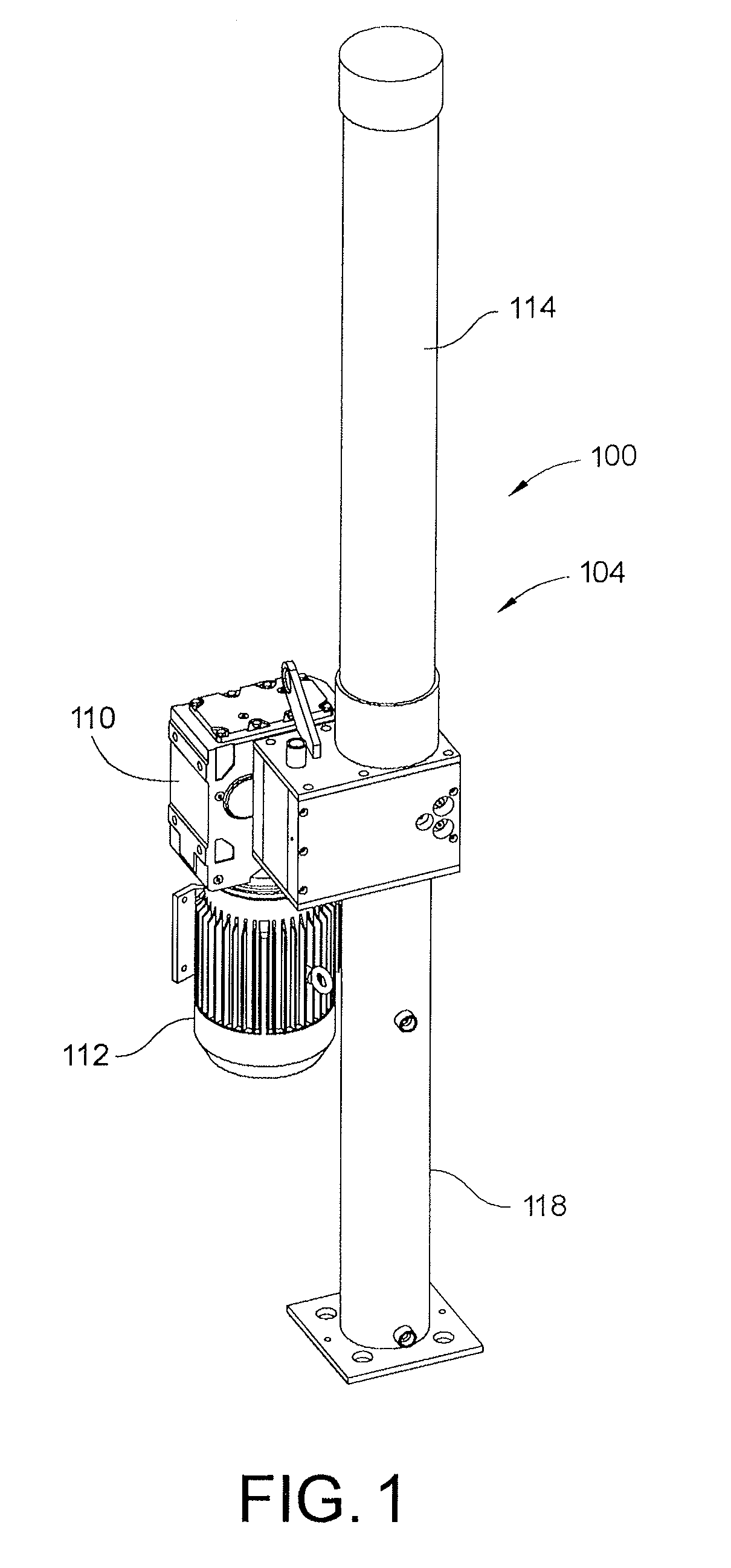
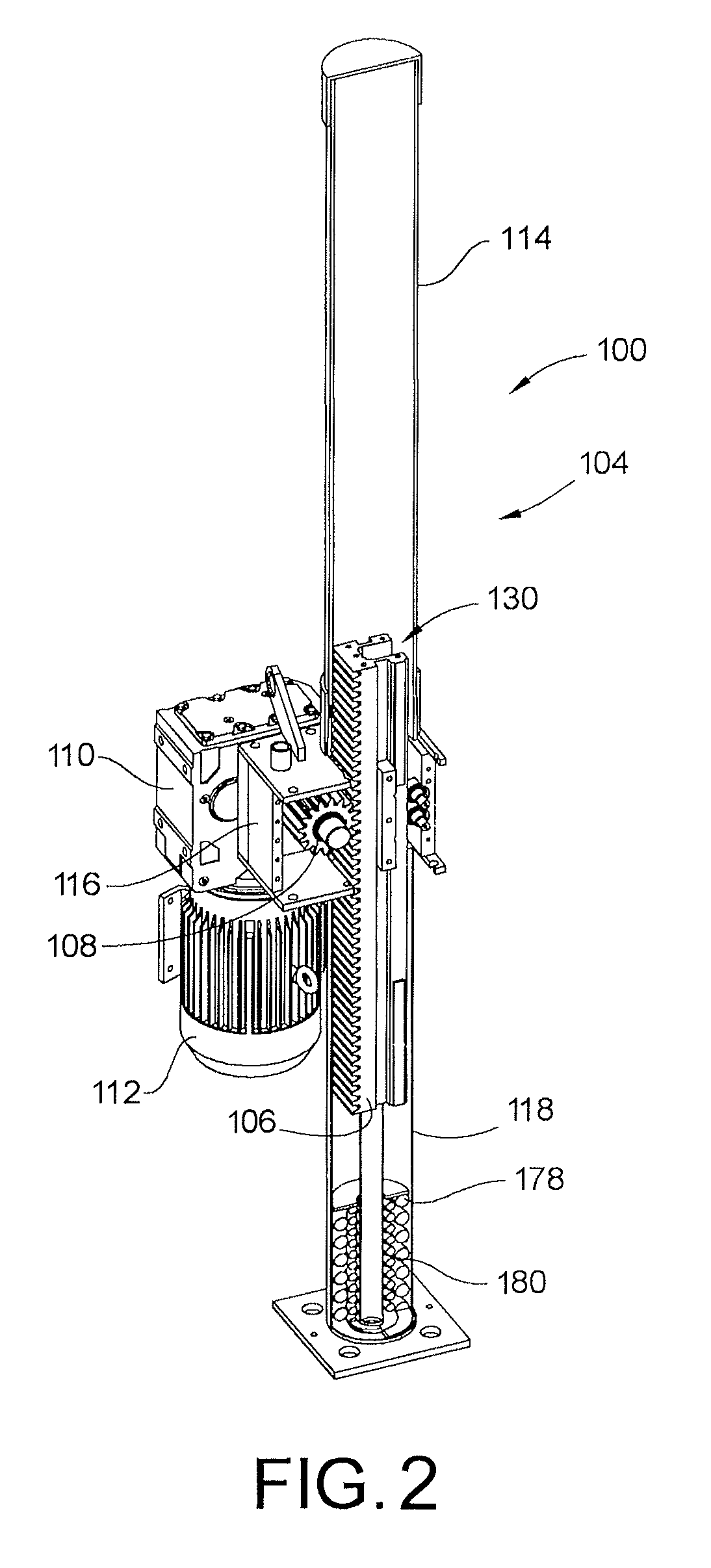
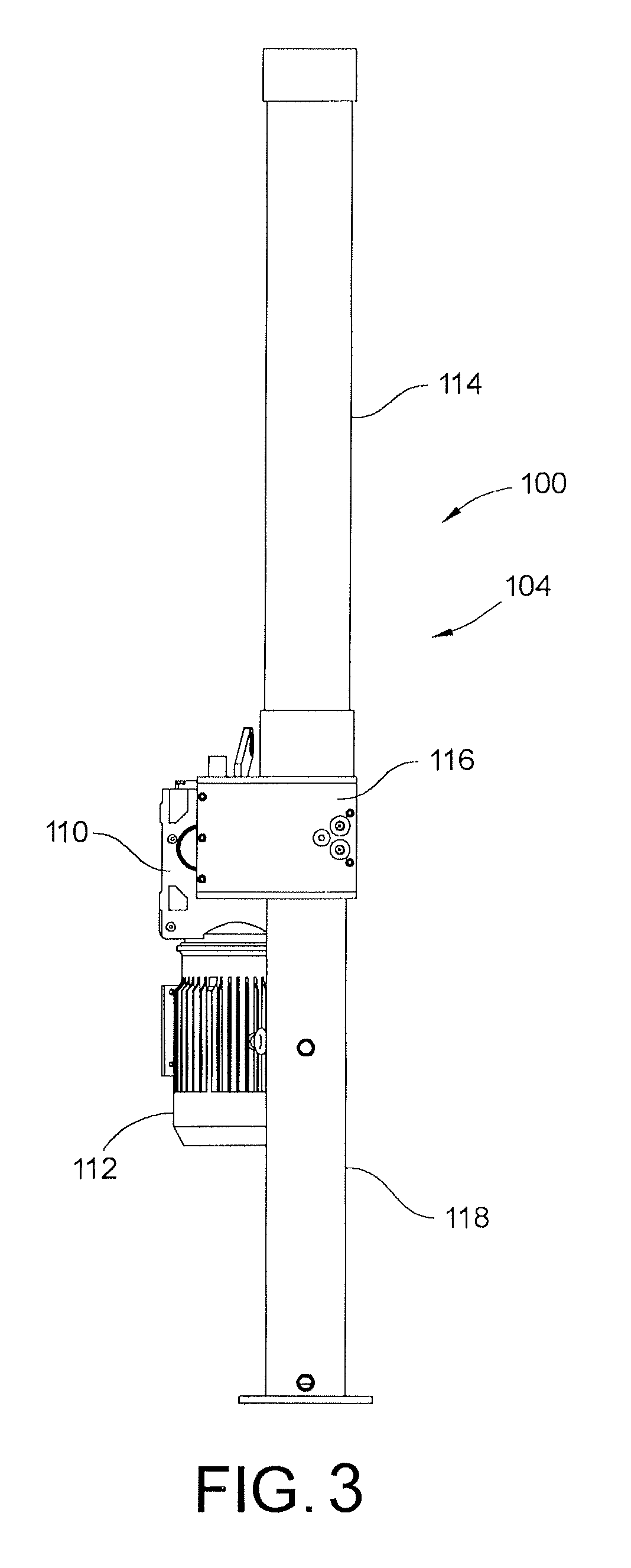
[0034]FIGS. 1 and 2 show a perspective view and a perspective cross-sectional view, respectively, of a linear rod pumping apparatus 100. FIG. 3 shows a plan view of the linear rod pumping apparatus 100. The linear rod pumping apparatus 100 includes a linear mechanical actuator system 104 which, in turn, includes a rack and pinion gearing arrangement having a rack 106 and a pinion 108 operatively connected through a gearbox 110 to be driven by a reversible electric motor 112 in a manner described in more detail below.

[0035]As shown schematically in FIGS. 2, 4, and 5, the linear mechanical actuator system 104 of the linear rod pumping apparatus 100 includes a rack and pinion gearing arrangement 106, 108 with the rack 106 being disposed for operation in a substantially vertical direction for reciprocating motion within a three piece housing having an upper, middle and lower section 114, 116, 118 along a substantially vertically-oriented pumping axis 120. The rack 106 is operatively con...


PUM


Abstract

A method for operating a tandem motor linear rod pumping apparatus that includes first and second linear mechanical actuator systems each having a motor, and also includes a rod for a sucker-rod pump. The method calls for constructing the first and second linear mechanical actuator systems to operate within a single housing, and simultaneously operating each of the two motors in a manner that imparts reciprocating vertical motion to respective-vertically movable members of the first and second linear mechanical actuator systems. Each motor has a reversibly rotatable element that is operatively connected to the vertically-movable member of its respective linear mechanical actuator system, thus establishing a fixed relationship between the rotational position of the rotatable element and the vertical position of its respective vertically-movable member. The simultaneous operation of the two motors imparts a reciprocating vertical motion to the pump rod of the sucker-rod pump.

Description

CROSS-REFERENCE TO RELATED PATENT APPLICATIONS[0001]This patent application is a divisional of co-pending U.S. patent application Ser. No. 15 / 283,934, filed Oct. 3, 2016, which claims the benefit of U.S. Provisional Patent Application No. 62 / 241,428, filed Oct. 14, 2015, the entire teachings and disclosures of which are incorporated herein by reference thereto.FIELD OF THE INVENTION[0002]This invention generally relates to systems and methods for the pumping of fluids, such as water and / or hydrocarbons, from subterranean formations or reservoirs, and more particularly to a pumping apparatus and method for use in such pumping applications.BACKGROUND OF THE INVENTION[0003]In many conventional types of pumping systems used in a drilling apparatus, controlling and optimizing the performance of a sucker-rod pumping apparatus involves inherent difficulties. One factor which must be taken into account is the stretching of the rod string, which occurs during the upward portion of each pump ...

Claims


Application Information

Patent Timeline
Patent Type & Authority Applications(United States)
IPC IPC(8): F04B19/22F04B17/03F04B53/10F04B51/00F04B49/06F04B9/04F04B47/02E21B43/12F04B53/14
CPCF04B19/22F04B17/03F04B53/1087F04B51/00F04B49/065F04B53/10F04B53/1032F04B9/047F04B47/022E21B43/127F04B49/06F04B47/02F04B53/14F04B9/02F04B53/20
Inventor HILGERS, ANDREW J.MACDONALD, MICHAEL A.GREGORY, BENJAMIN J.PETERSON, RONALD G.
Owner UNICO LLC
Why Eureka
Try Eureka