
Bench anchor
a technology for woodworking benches and anchors, which is applied to work benches, fastening means, dowels, etc., can solve the problems of large devices, more expensive than they need, and limited usability, and achieves less expensive, convenient use, and reduced costs.
- Summary
- Abstract
- Description
- Claims
- Application Information
AI Technical Summary
Benefits of technology
Problems solved by technology
Method used
Image

Examples
embodiment 10
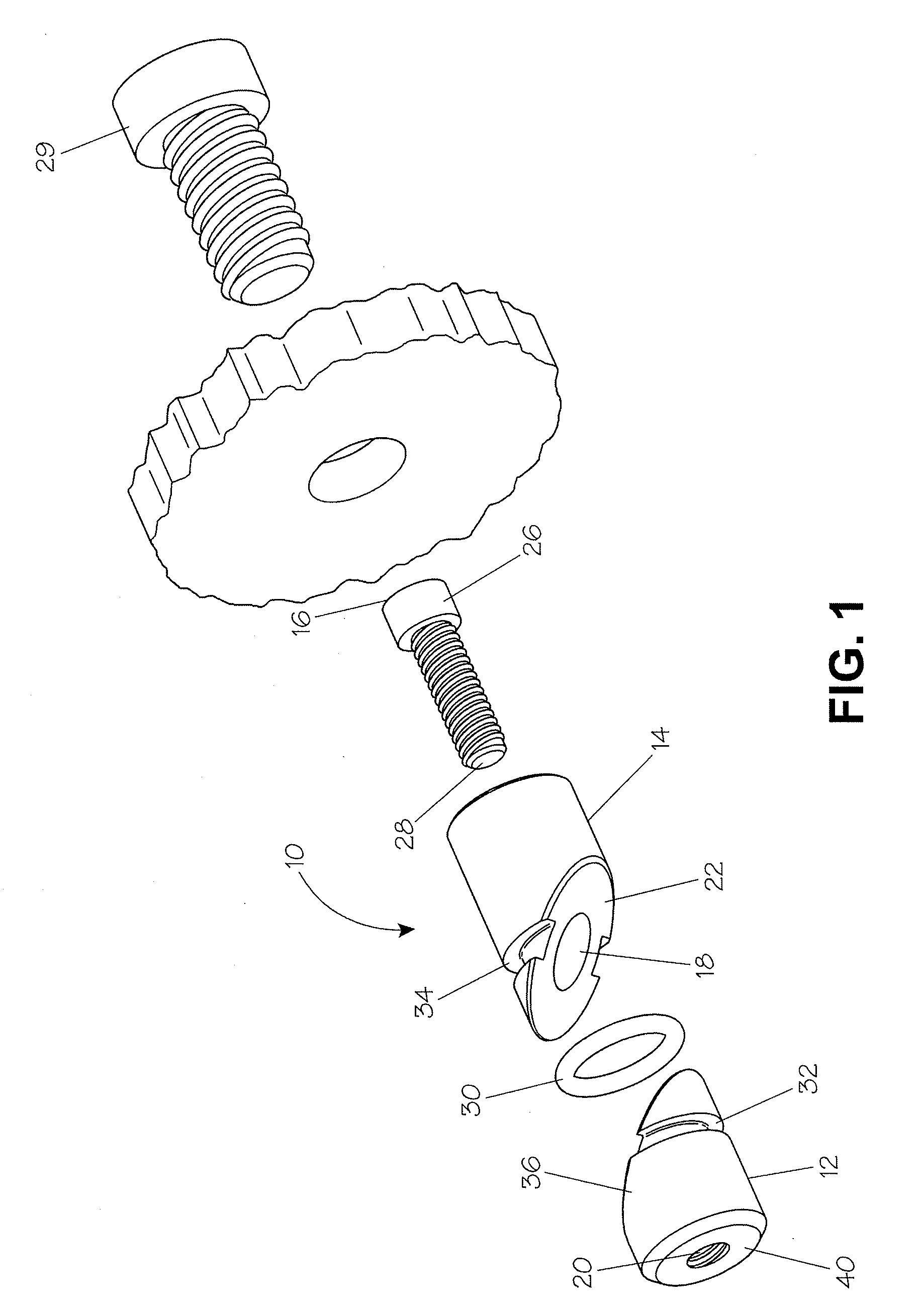
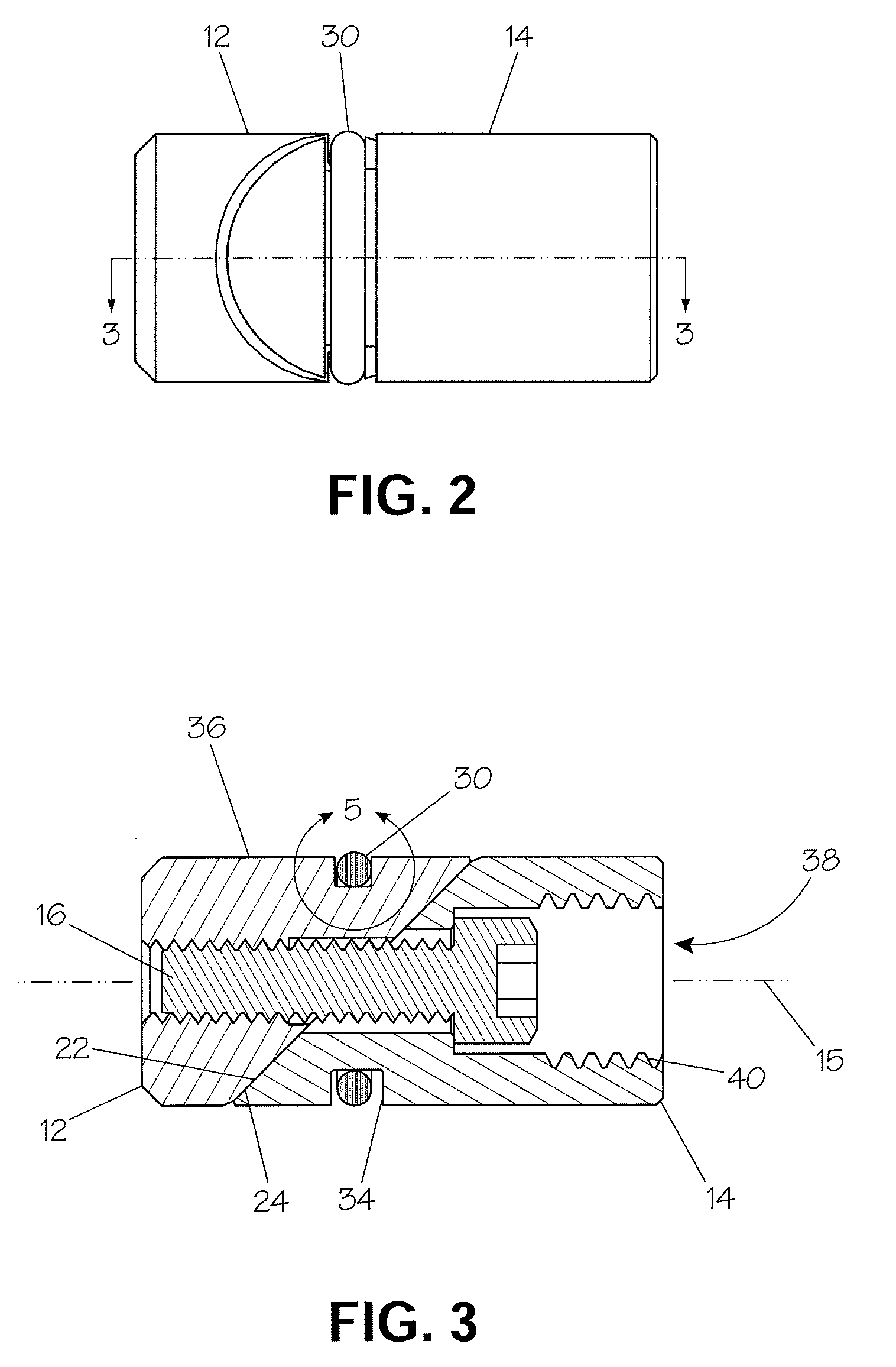
[0025]While the anchor 10 and other embodiments of this invention can be produced in a wide variety of sizes and configurations and of a wide variety of materials, a desirable diameter for the base 12 and head 14 of the cylindrical embodiment 10 illustrated in the figures (and intended for use in a round dog hole) is 0.740 inches. This provides 0.010 inches of clearance within a ¾ inch dog hole. Among other materials useable for the base 12 and head 14 are low malleability materials such as steel, iron, brass or engineering plastics. In a well-functioning nominally ¾ inch diameter anchor 10, the O-ring 30 can protrude from groove 32 by an amount “x” (see FIG. 5) of approximately 0.015 inches. For instance, the diameter of the O-ring 30 material may be 0.103 inches, and the depth of groove 32 can be 0.088 inches. Different amounts of protrusion may be desirable depending on the nominal diameter and weight of the anchor 10 and depending on the properties of the O-ring 30 and possibly ...
embodiment 100
[0035]As is described above, the embodiment 10 of this anchor is typically designed to operate within a ¾″ round dog hole. However, appropriately sized, otherwise comparable anchors could be used in round dog holes of other diameters. Furthermore, another alternative embodiment would be made using square or rectangular cross section counter-wedges for use in square or rectangular dog holes, a hole shape found on many older benches and some benches still being manufactured. Such a square cross section embodiment 100 of the anchor of this invention is illustrated in FIG. 18, where the base 120 is attached to a head 120 with a screw 16, and an O-ring 30 encircles these components and seats in a groove 340 in head 140 and a groove 320 in base 120.
[0036]The present embodiment calls for the O-ring to project from the lower wedge and to be recessed within the upper wedge. However, the same function could be achieved it the O-ring projected from both wedges. The drawback to this configurati...
PUM
 Abstract
Description
Claims
Application Information